background image

{

{

{


8


8


8

10”

1”

p.


19

 - M

anu

al 

FA

0

1

2

0

6

-E

N

 - 0

6

/2

0

18 - © C

A

M

E S

.p

.A

. - T

ransla

te

d o

riginal inst

ru

ct

io

ns

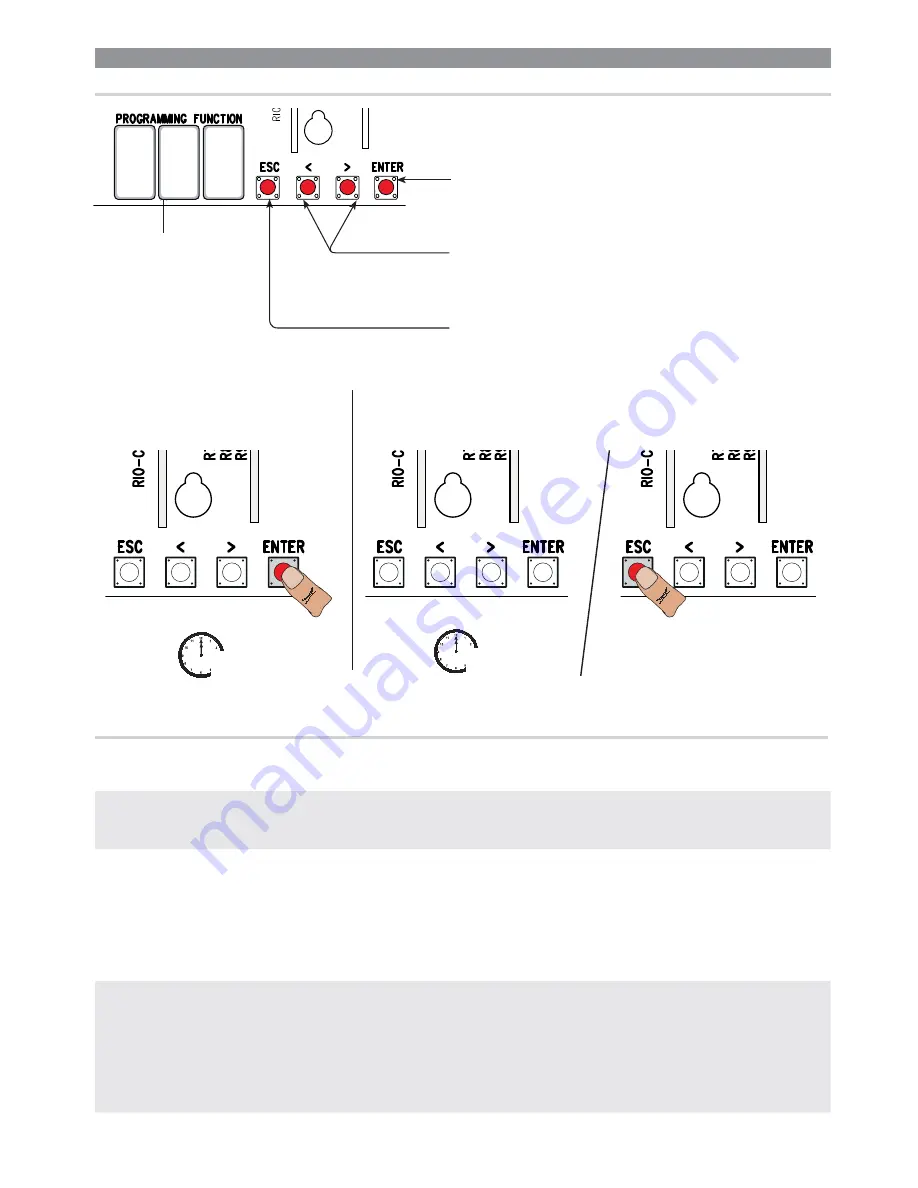
The < > keys are for:
- moving from one item to another;
- increasing or decreasing a value;
- opening and closing the gate (only when testing).

The ESC button is for:
- exiting menus;
- deleting changes;
- stopping the gate (only when testing).

The ENTER key is for:
- entering menus;
- confirming or memorizing set values.


To exit the menu, wait 10 seconds or press ESC.


 To enter the menu, keep the ENTER button 

pressed for at least one second.

Display

PROGRAMMING

DESCRIPTION OF THE COMMANDS

F1

Total stop [1-2]

NC input – Gate stop that excludes any automatic closing; to resume movement, use the control device. The 
safety device is inserted into (1-2). If unused, select 0.

OFF

 (

default

) / 

ON

F2

Input [2-CX]

NCinput – Can associate: C1 = reopening during closing by photocells, C2 = reclosing during opening by 
photocells, C3 = partial stop, C4 = obstruction wait, C7 = reopening during closing by sensitive safety-edges 
(with clean contact), C8 = reclosing during opening by sensitive safety-edges (with clean contact), r7 = 
reopening during closing for sensitive safety edges (8K2 resistive input), - r8 = reclosing during opening for 
sensitive safety edges (8K2 resistive input).


 The C3 Partial stop function only appears if the F 19 Automatic closing time function is activated.

OFF

 (

default

) / 

1

=C1 / 

2

=C2 / 

3

=C3 / 

4

=C4 / 

7

=C7 / 

8

=C8 / 

r7

=r7 / 

r8

=r8

F3

Input [2-CY]

NC input – Can associate: C1 = reopening during closing by photocells, C2 = reclosing during opening by 
photocells, C3 = partial stop, C4 = obstruction wait, C7 = reopening during closing by sensitive safety-edges 
(with clean contact), C8 = reclosing during opening by sensitive safety-edges (with clean contact), r7 = 
reopening during closing for sensitive safety edges (8K2 resistive input), - r8 = reclosing during opening for 
sensitive safety edges (8K2 resistive input).


 The C3 Partial stop function only appears if the F 19 Automatic closing time function is activated.

OFF

 (

default

) / 

1

=C1 / 

2

=C2 / 

3

=C3 / 

4

=C4 / 

7

=C7 / 

8

=C8 / 

r7

=r7 / 

r8

=r8


When programming, the operator needs to be in stop mode.

FUNCTIONS MENU

Summary of Contents for BX704ALS

Page 1: ...BX704ALS BX708ALS Sliding gate operator BX series INSTALLATION MANUAL EN English FA01206 EN ...

Page 2: ...2 3 1 2 3 1 ...

Page 3: ...ell fastened to the ground entirely above the surface and free of any impediments to the gate s movement The rails of the upper guide must not cause any friction Make sure that opening and closing limiters are fitted Make sure the operator is installed onto a sturdy surface that is protected from any collisions Make sure that mechanical stops are already installed If the operator is installed lower...

Page 4: ...ocks Do not install of use this device in any way except as specified in this manual INTENDED USE Model BX704ALS BX708ALS Standard reference length of the sliding part m 4 Maximum weight of the sliding part kg 400 800 Pinion module 4 For other than standard measurements see the following graphs TECHNICAL DATA Datum BX704ALS BX708ALS Protection rating IP 44 Power supply V 50 60 Hz 230 AC Input volt...

Page 5: ...es hour no 17 Consecutive cycles no 6 The cycles calculation refers to a gate that has a standard reference length see the intended use that are professionally installed free of any mechanical issues and or accidental friction points and measured at 20 C as stated in EN Standard 60335 2 103 When using other than standard measurements see the graphs below Number of cycles Number of cycles Length of...

Page 6: ...ing light 7 Photocells 8 Posts 9 Mechanical gate stop 10 Sensitive safety edge 11 Junction pit DESCRIPTION OF PARTS 1 Cover 2 Front cover 3 Gear motor 4 Condenser 5 Mechanical limit switch 6 Anchoring plate 7 Control board rack 8 ZBX7N control board 9 Limit switch fins 10 Transformer 11 Release hatch 12 Fastening hardware 13 Mounting brace for housing accessories optional ...

Page 7: ...TYPES AND MINIMUM THICKNESSES Connection cable length 20 m 20 30 m Input voltage for 230 V AC control board 1P N PE 3G x 1 5 mm 2 3G x 2 5 mm 2 Flashing light 2 x 0 5 mm 2 Command and control devices 2 x 0 5 mm 2 TX Photocells 2 x 0 5 mm 2 RX photocells 4 x 0 5 mm 2 When operating at 230 V and outdoors use H05RN F type cables that are 60245 IEC 57 IEC compliant whereas indoors use H05VV F type cab...

Page 8: ... surface Wait at least 24 hrs for the concrete to solidify Fit the bolts into the anchoring plate and tighten them using the nuts Remove the pre shaped clamps using a screw driver or pliers Place the plate over the iron cage Careful The tubes must pass through their corresponding holes FITTING THE ANCHORING PLATE Set up a foundation frame that is larger than the anchoring plate and sink it into th...

Page 9: ...CAME S p A Translated original instructions Remove the foundation frame and fill the hole with earth around the concrete block Remove the nuts from the bolts Fit the electric cables into the tubes so that they come out about 600 mm ...

Page 10: ... must pass under the gearmotor casing and must not touch any parts that may overheat during use such as the motor or the transformer and so on Lift the gearmotor by 5 to 10 mm from the plate by adjusting the threaded steel feet to allow any subsequent adjustments between pinion and rack SETTING UP THE OPERATOR Removethe front cover and the operator casing ...

Page 11: ...izontal adjustment This prevents the gate s weight from bearing down on the operator FASTENING THE RACK If the rack is already set up the next step should be to adjust the rack and pinion coupling distance otherwise fasten it release the operator rest the rack above the operator pinion weld or fasten the rack to the gate along its entire length To assemble the rack modules use an extra piece and r...

Page 12: ...ate using the supplied hardware Spring For closing close the gate q fit the closing limit switch tab into the rack until the micro switch is activated spring and fasten it using the grub screws rs ESTABLISHING THE LIMIT SWITCH POINTS For opening open the gate n fit the opening limit switch tab onto the rack until the micro switch activates spring and fasten it using the grub screws op ...

Page 13: ...ls 3 Transformer terminals 4 Control board fuse 5 Terminals for control and safety devices 6 Fuse accessories 7 Terminals for the RGP1 module 8 Encoder terminals 9 Keypad selector terminal 10 Terminals for limit switch micro switches 11 Antenna terminal 12 AF card slot 13 Terminals for transponder selector 14 Terminals for paired of CRP connection 15 Connector for the R700 R800 R900 card 16 Connec...

Page 14: ...he law Before connecting all the wires set up the cables by using cable glands on the control board brace as shown in the figure The electrical cables must not touch any heated parts such as the motor transformer and so on WHITE RED ORANGE Mechanical limit switch Opening limit switch micro switch Condenser 120 230V AC gear motor with Encoder Closing limit switch micro switch FACTORY WIRING ...

Page 15: ...ies power supply output 24 V AC max 20 W To change the motor torque plug the faston terminal as shown into one of the four positions from 1 min to 4 max 120 230 V AC 50 60 Hz POWER SUPPLY Flashing light connection output contact rated for 230 V AC 25 W max and or additional light contact rated for 230 V 60 W max See functionF18 SIGNALING DEVICES Gate closed warning output contact rated for 24 V AC...

Page 16: ...d e g the AF R800 you MUST CUT OFF THE MAIN POWER SUPPLY and remove any batteries PARTIAL OPENING function from control device NO contact OPEN CLOSE INVERT step step function from control device NO contact Alternatively from the functions programming you can activate the single command OPEN STOP CLOSE STOP sequential See functionF7 STOP button NC contact For stopping the gate while excluding autom...

Page 17: ...ng opening the contact triggers the inversion of movement until the gate is completely closed C3 partial stop Stopping of the gate if it is moving with consequent automatic closing if the automatic closing function has been entered C4 obstruction wait Stopping of the gate if it is moving which resumes movement once the obstruction is removed If contacts CX and CY are not used they should be deacti...

Page 18: ...rd WARNING For the system to work properly before fitting the control board you MUST CUT OFF THE POWER MAINS and remove any emergency batteries Serial RS485 connection via CRP Came Remote Protocol or for paired operation see chapter called PAIRED OPERATION Sensitive Safety Edges Configure contact CX or CY NC safety input for sensitive safety edges See functionsF2 input CX or F3 input CY in C7 sens...

Page 19: ...g closing by sensitive safety edges with clean contact C8 reclosing during opening by sensitive safety edges with clean contact r7 reopening during closing for sensitive safety edges 8K2 resistive input r8 reclosing during opening for sensitive safety edges 8K2 resistive input The C3 Partial stop function only appears if the F 19 Automatic closing time function is activated OFF default 1 C1 2 C2 3...

Page 20: ...hing light default 1 Cycle F19 Automatic Closing Time The automatic closing wait starts when the opening limit switch point is reached and can be set to between 1 and 180 seconds The automatic closing does not work if any of the safety devices trigger when an obstruction is detected or after a total stop or during a power outage OFF default 1 1 second 180 180 seconds F20 Automatic closing time aft...

Page 21: ...e available P0 stop gate and exclude any automatic closing to resume movement use the control device P7 reopening during closing P8 reclosing during opening For programming see the instructions that come with the accessory This function only appears if the RIOCN8WS card is plugged into the control board OFF default P0 P0 P7 P7 P8 P8 F66 Wireless input RIO EDGE T2 RIO EDGE wireless safety device as...

Page 22: ...af swing see the CALIBRATING SWING paragraph This function only appears if function F11 is activated If the operator is not calibrated it excludes all commands OFF default ON A 4 Resetting parameters Caution The default settings will be restored OFF default ON A 5 Maneuver count It is for viewing the number of maneuvers done OFF default ON H 1 Version View the firmware version SETTING UP Once the e...

Page 23: ... an opening maneuver until it reaches a final stop MANAGING USERS When adding and deleting users the flashing numbers appearing are those numbers that are available and usable to assign to a new user max 250 users Before registering the users make sure the AF radio card is plugged into the connector see the paragraph called CONTROL DEVICES ENTERING USERS WITH AN ASSOCIATED COMMAND Select U 1 Press...

Page 24: ...29 130 131 132 133 134 135 136 137 138 139 140 141 1 2 3 4 5 6 7 8 9 10 11 12 13 14 15 16 17 18 19 20 21 22 23 24 25 26 27 28 29 30 31 32 33 34 35 36 37 38 39 40 41 42 43 44 45 46 47 48 49 50 51 52 53 54 55 56 57 58 59 60 61 62 63 64 65 66 67 68 69 70 71 72 73 74 75 76 77 78 79 80 81 82 83 84 85 86 87 88 89 90 91 92 93 94 95 96 97 98 99 100 101 102 103 104 105 106 107 108 109 110 111 112 113 114 1...

Page 25: ...52 153 154 155 156 157 158 159 160 161 162 163 164 165 166 167 168 169 170 171 172 173 174 175 176 177 178 179 180 181 182 183 184 185 186 187 188 189 190 191 192 193 194 195 196 197 198 199 200 201 202 203 204 205 206 207 208 209 210 211 212 213 214 215 216 217 218 219 220 221 222 223 224 225 226 227 228 229 230 231 232 233 234 235 236 237 238 239 240 241 242 243 244 245 246 247 248 249 250 u 2 2...

Page 26: ...rror messages appear on the display Memory roll Memory roll SAVING AND UPLOADING ALL DATA USERS AND CONFIGURATION WITH THE MEMORY ROLL Procedure for memorizing all of the system s user and configuration data by using the Memory Roll so they can be used with another control board even on another system Caution Fitting and extracting the Memory Roll must be done with the mains power disconnected Fit...

Page 27: ... gate travel calibration The programming keys on the SLAVE control panel are disabled Operating modes n Either STEP STEP or ONLY OPEN command Both leaves open oPARTIAL PEDESTRIAN OPENING command Only the MASTER operator s leaf opens For the types of command that can be selected and paired to users see the ENTERING USERS WITH ASSOCIATED COMMANDS DISMANTLING AND DISPOSAL CAME S p A applies a certifi...

Page 28: ...ella Libertà 15 31030 Dosson di Casier Treviso Italy tel 39 0422 4940 fax 39 0422 4941 Manual FA01206 EN 06 2018 CAME S p A Translated original instructions The contents of this manual may change at any time and without notice ...

Reviews: