background image

Chapter 3:  System planning 

Wireless 


Page 

3-32


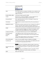
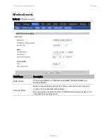
Wireless 

Basic 

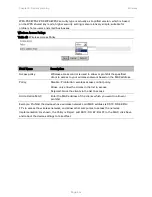
Table 35  Basic 


Field Name 

Description 

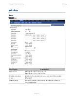
Radio on/off 

Select “Radio off” to disable wireless. 
Select “Radio on” to enable wireless. 

Wireless connection 
mode 

According to the wireless client type, select one of these modes. 
Default is AP 

Network Mode 

Choose one network mode from the drop down list. Default is  
11b/g/n mixed mode  

Summary of Contents for cnPilot Home R200

Page 1: ...Cambium cnPilot Home Small Business Wireless Router User Guide System Release V4 2 For R200x and R201x modeles...

Page 2: ...ghted material Accordingly any copyrighted material of Cambium its licensors or the 3rd Party software supplied material contained in the Cambium products described in this document may not be copied...

Page 3: ...llation and Setup via cnMaestro 1 6 Accessing and Configuring cnPilot Devices via cnMaestro 1 7 Accessing cnMaestro and Beginning Setup Configuration 1 7 Accessing and Configuring cnPilot Devices via...

Page 4: ...ce 4 2 Login to cnMaestro 4 3 On Boarding of cnPilot R200 R201 4 5 On Boarding using Serial Number 4 5 Onboarding using Cambium ID 4 6 Configuring the Devices 4 7 Basic Details 4 7 Set Device Location...

Page 5: ...igure 2 Login Prompt WAN Port 2 3 Figure 3 Multi VLAN 3 13 Figure 4 Multi WAN network 3 14 Figure 5 Basic details 4 7 Figure 6 Select Location 4 8 Figure 7 Firmware update 4 8 Figure 8 Configure devic...

Page 6: ...ent Interface 2 11 Table 13 Registration status 2 12 Table 14 Login details 3 2 Table 15 Status Page 3 3 Table 16 Internet 3 6 Table 17 DHCP 3 7 Table 18 PPPoE 3 8 Table 19 Bridge Mode 3 10 Table 20 C...

Page 7: ...settings 3 59 Table 58 Adding one dial plan 3 60 Table 59 Dial Plan 3 60 Table 60 Blacklist 3 62 Table 61 Call log 3 63 Table 62 Filtering setting 3 66 Table 63 Content filtering 3 67 Table 64 UPnP 3...

Page 8: ...Tables Page vi Table 83 Operating mode 3 107 Table 84 System log 3 108 Table 85 Logout 3 108...

Page 9: ...lity to act as a stand alone router if desired In addition to WiFi this product provides high quality voice calls as well as the optional ability to power Cambium s ePMP series subscriber module or th...

Page 10: ...ort Main website http www cambiumnetworks com Sales enquiries solutions cambiumnetworks com Support enquiries support cambiumnetworks com Repair enquiries rma cambiumnetworks com Telephone number list...

Page 11: ...he customer or anyone acting on the customer s behalf to abide by the instructions system parameters or recommendations made in this document Cross references References to external publications are s...

Page 12: ...to radio communications However there is no guarantee that interference does not occur in a particular installation Note Changes or modifications not expressly approved by the party responsible for c...

Page 13: ...ng format Warning Warning text and consequence for not following the instructions in the warning Cautions Cautions precede instructions and are used when there is a possibility of damage to systems so...

Page 14: ...cnPilot Home R200x R201x cnPilot Home R200x LED Indicators and Interfaces cnPilot Home R201x LED Indicators and Interfaces Hardware Installation and Setup via cnMaestro Accessing and Configuring cnPil...

Page 15: ...RJ45 4xGE in RJ45 Wi Fi 2X2 2 4GHz 802 11 b g n 2X2 2 4GHz 802 11 b g n 300 Mbps No 2X2 5GHz 802 11ac 867 Mbps USB 1X USB 2 0 1X USB 2 0 VoIP 2xFXS in RJ111 2xFXS in RJ111 No Cambium PoE Power over E...

Page 16: ...ed On Green Registered LAN 1 2 3 4 On Green Port is connected at 100 Mbps Off The port is disconnected Blinking Green Transmitting data WAN On Green Port is connected with 100 Mbps Off The port is dis...

Page 17: ...terfaces Page 1 4 Table 3 cnPilot Home R200x Interfaces Rear Panel Interface Description POWER Connector for a power adapter Phone1 2 ATA Analog phone connector USB USB interface WAN Connector for acc...

Page 18: ...ort is connected at 100 Mbps WAN Off The port is disconnected Blinking Green The data is transmitting On Green The port is connected at 100 Mbps LAN 1 2 3 4 Off The port is disconnected Blinking Green...

Page 19: ...damage the cnPilot Home R200x R201x and will void the manufacturer warranty Warning Changes or modifications not expressly approved by the party responsible for compliance can void the user s authori...

Page 20: ...atest information on operating these features at the Cambium Community Forum Register at Cambium s support forum http community cambiumnetworks com for instructions discussions and helpful tips on man...

Page 21: ...sing an Ethernet cable 3 If desired connect one of 4 available LAN ports to your PC or networked device with an Ethernet cable cnPilot Home devices allow you to connect up to 4 PCs or other Ethernet c...

Page 22: ...adiate radio frequency energy and if not installed and used in accordance with the instructions may cause harmful interference to radio communications However there is no guarantee that interference w...

Page 23: ...to enter password directly For example WEB login password is admin so the password in IVR is admin The user may 23646 to access and then configure the WAN connection port The unit reports Operation Su...

Page 24: ...168 20 1 4 Press key to indicate that you have finished Report operation successful if user operation is ok 5 To quit press 5 DNS 1 Pick up phone and press to start IVR 2 Choose 5 and cnPilot Home R20...

Page 25: ...method of inputting password is same as operation 1 4 If user wants to quit press 5 Report operation successful if user operation is ok 9 WEB Access Port 1 Pick up phone and press to start IVR 2 Choos...

Page 26: ...address subnet mask and default gateway is required to complete the configuration If in DHCP mode please make sure that a DHCP server is available in your existing broadband connection to which WAN p...

Page 27: ...Page 2 1 Chapter 2 Configuring Basic Settings This chapter covers Two Level Management Web Management Interface Configuring Making a Call...

Page 28: ...below for information Logging in from the LAN port Ensure your PC is connected to the router s LAN port correctly Note You may either set up your PC to get an IP dynamically from the router or set up...

Page 29: ...o Network WAN Open a web browser on your PC and type http IP address of WAN port The following login page will be opened to enter username and password Figure 2 Login Prompt WAN Port For administrator...

Page 30: ...tiple options in the Sub navigation bar are displayed Sub navigation bar Click the Sub navigation bar to choose a configuration page area marked as 2 Parameter configuration This area displays the cur...

Page 31: ...Current Time When NTP Enable is set to Disable manually configure the time and date via the Current Time parameter Sync with host Press button to synchronize the host PC date time and time zone Primar...

Page 32: ...net Connection setting see Table 9 below Table 9 Configuring an internet connection Field Name Description Connect Name Use keywords to indicate WAN port service model the parameters are defined in Ne...

Page 33: ...evice under LAN port will automatically obtains the preferred DNS and alternate DNS 2 When DNS mode is Manual the user should manually configure the preferred DNS and alternate DNS Primary DNS Enter t...

Page 34: ...o disable wireless operation Select Radio on to enable wireless operation Please note Save required for this parameter change Network Mode Choose one network mode from the drop down list SSID The logi...

Page 35: ...s connected to the router via one of the Multiple SSIDs are visible on the network to each other BSSID Basic Service Set Identifier AP MAC Address Listing Frquency Channel Select the channel of operat...

Page 36: ...e and ask you to offer additional configuration For high security the device can be configured for Security Mode as WPA2 PSK and WPA Algorithms as AES WPA Algorithms This parameter is used to select t...

Page 37: ...nt Interface Table 12 Configuring SIP via the Web Management Interface Procedure 1 Open the FXS1 FXS2 SIP Account webpage as illustrated above 2 Fill the SIP Server address and SIP Server port number...

Page 38: ...ettings Web Management Interface Details Page 2 12 Viewing the Registration Status Table 13 Registration status Procedure To view the SIP account status of device open the Status webpage and view the...

Page 39: ...vice i e another ATA or other SIP products have public IP addresses or Both ATA and the other VoIP device i e another ATA or other SIP products are on the same LAN using private or public IP addresses...

Page 40: ...s 78 to transfer to C then B and C now in conversation If the transfer is not completed successfully then A and B are in conversation again Conference Assume that call party A and B are in a conversat...

Page 41: ...chapter guides users to execute advanced full configuration through admin mode operation This chapter covers Login Status Network and Security Wireless SIP FXS1 FXS2 Security Application Administrati...

Page 42: ...Page 3 2 Login Table 14 Login details Procedure 1 Connect the LAN port of the router to your PC vi an Ethernet cable 2 Open a web browser on your PC and type http 192 168 11 1 3 Enter Username admin a...

Page 43: ...Chapter 3 System planning Status Page 3 3 Status Table 15 Status Page...

Page 44: ...Chapter 3 System planning Status Page 3 4...

Page 45: ...m planning Status Page 3 5 Description This webpage shows the status information about the Product Network and System including Product Information SIP Account Status FXS Port Status Network Status an...

Page 46: ...t providers In most cases a Cable service provider will offer a fixed public IP while a DSL service provider will offer a public subnet If you have a public subnet you can assign an IP address to the...

Page 47: ...ally Table 17 DHCP Field Name Description DNS Mode Select DNS mode options are Auto and Manual When DNS mode is Auto the device under LAN port will automatically obtain the preferred DNS and alternate...

Page 48: ...thernet can share a common connection PPPoE is used for most of DSL modem users All local users can share one PPPoE connection for accessing the Internet Your service provider will provide you informa...

Page 49: ...n Demand and Manual When the mode is Keep Alive the user sets the keep alive redial period values range from 0 to 3600s the default setting is 5 minutes When the mode is On Demand the user sets the on...

Page 50: ...e connection for host of LAN port Table 19 Bridge Mode Field Name Description Bridge Type IP Bridge Allow all Ethernet packets to pass PC can connect to upper network directly PPPoE Bridge Only Allow...

Page 51: ...ts connected to the LAN port can get IP from DHCP server run in gateway VLAN Mode Disable The WAN interface is untagged LAN is untagged Enable The WAN interface is tagged LAN is untagged Trunk Only va...

Page 52: ...nternet applications VOICE The connection supports voice applications like SIP and RTP TR069_VOICE The connection supports both management and voice applications VOICE_INTERNET The connection supports...

Page 53: ...nsmission VOICE VLAN supports voice transmission and TR069 VLAN supports WEB Telnet and TR069 services transmission Figure 3 Multi VLAN There are several advanced functions available when using Multi...

Page 54: ...y Page 3 14 Figure 4 Multi WAN network Setting up the Internet Connection From the WAN page a multi WAN connection can be created or deleted See below for more information on configuring these setting...

Page 55: ...069_VOICE_INTERNET The connection supports management voice and Internet applications Other The connection support STB NAT Mode B Bridge R Router VLAN ID VID VLAN ID For example 1_TR069_R_VID_2 First...

Page 56: ...Pass Through DHCP packets are forwarded between the WAN interface and the LAN interface the DHCP server in the device will not allocate IP to clients of the LAN port DHCP Snooping When the device for...

Page 57: ...r in the device VLAN Mode Disable The WAN interface is untagged LAN is untagged Enable The WAN interface is tagged LAN is untagged Trunk Only valid in bridge mode All ports including WAN and LAN belon...

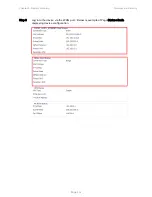
Page 58: ...Step 1 Login to the web management interface of the cnPilot Device Navigate to Page Administration Operating Mode Set Operating mode to Basic Mode Click Save Step 2 Open Network WAN Change NAT Enable...

Page 59: ...Chapter 3 System planning Network and Security Page 3 19 Step 3 Log into the device via the WAN port Below is example of Page Status Basic displaying device configuration...

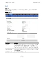
Page 60: ...ss Enter the IP address of the router on the local area network All the IP addresses of the computers which are in the router s LAN must be in the same network segment with this address and the defaul...

Page 61: ...Manual 1 When DNS mode is Auto the device under LAN port will automatically obtains the preferred DNS and alternate DNS 2 When DNS mode is Manual the user should manually configure the preferred DNS...

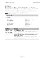
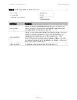
Page 62: ...that you leave the router enabled as a DHCP server if you do not have a DHCP server for your network Table 24 DHCP server settings Field Name Description Local DHCP Server Enable Disable DHCP server...

Page 63: ...202 96 134 33 to this field Secondary DNS Specify the Secondary DNS address provided by your ISP If your ISP does not provide this address the router will automatically apply default Secondary DNS Se...

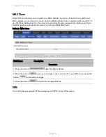
Page 64: ...dress button the computer accessing the web management interface will have the MAC address automatically entered in the Clone WAN MAC field Table 26 MAC clone Field Name Description Procedure 1 Press...

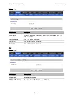
Page 65: ...If the VPN is enabled user can select PPTP and L2TP mode VPN Initial Service IP Enter VPN server IP address User Name Enter authentication username Password Enter authentication password DMZ Table 28...

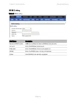
Page 66: ...S setting Field Name Description Dynamic DNS Provider DDNS is enabled and select a DDNS service provider Account Enter the DDNS service account Password Enter the DDNS service account password DDNS En...

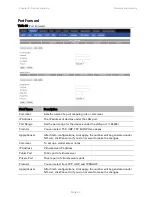
Page 67: ...DP three cases Apply Cancel After finish configurations click apply the number will be generated under NO List click Cancel to if you do not want to make the changes Comment To set up a virtual server...

Page 68: ...lue which the cnPilot Home R200x can provide Mss Mode Choose Mss Mode from Manual and Auto Mss Value Set the value of TCP AntiDos p You can choose to enable or prohibit IP conflict detection Select en...

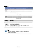
Page 69: ...ort Setting Table 32 Port setting Field Name Description WAN Port speed Nego Auto negotiation options are Auto 100M full 100M half duplex 10M half and full LAN1 LAN4 Port Speed Nego Auto negotiation o...

Page 70: ...isable QoS function Upstream Set the upstream bandwidth Downstream Set the downstream bandwidth Delete Selected In NO Check the items you want to delete click the Delete option Add Click Add to add a...

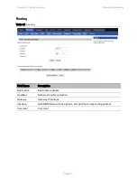
Page 71: ...y Page 3 31 Routing Table 34 Routing Field Name Description Destination Destination address Host Net Both Host and Net selection Gateway Gateway IP address Interface LAN WAN Custom three options and a...

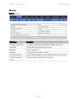
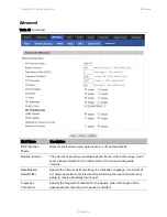
Page 72: ...scription Radio on off Select Radio off to disable wireless Select Radio on to enable wireless Wireless connection mode According to the wireless client type select one of these modes Default is AP Ne...

Page 73: ...nsists of a basic access device BSS each computer in the BSS must be configured with the same BSSID that is the wireless AP logo Frequency Channel You can select Auto Select and channel 1 2 3 4 5 6 7...

Page 74: ...le Block Acknowledgement frame Disabled Auto block acknowledgement is not used by the device use this configuration when low throughput connectivity issues are experienced by mobile devices Decline BA...

Page 75: ...ion SSID Choice Choose one SSID from SSID Multiple SSID1 Multiple SSID2 and Multiple SSID3 Security Mode Select an appropriate encryption mode to improve the security and privacy of your wireless data...

Page 76: ...Table 37 WiFI Security Setting Field Name Description Security Mode This is used to select one of the 4 WEP keys key settings on the clients should be the same with this when connecting WEP Keys Set t...

Page 77: ...se Setting up WPA PSK security password Key Renewal Interval Set the key scheduled update cycle default is 3600s WPAPSKWPA2PSK manner is consistent with WPA2PSK settings Table 39 WPAPSKWPA2PSK Field N...

Page 78: ...client to access to your wireless network based on the MAC address Policy Disable Prohibition wireless access control policy Allow only allow the clients in the list to access Rejected block the clie...

Page 79: ...i Multi Media is the QoS certificate of Wi Fi Alliance WFA This provides you to configure the parameters of wireless multimedia WMM allows wireless communication to define a priority according to the...

Page 80: ...onnection between wireless station and wireless access point with the encryption of WPA and WPA2 It is the simplest way to build connection between wireless network clients and wireless access point U...

Page 81: ...ble WPS function WPS Summary Display the current status of WPS including current state SSSID name authentication methods encryption type and the PIN code of this AP Generate Generate a new PIN code Re...

Page 82: ...button directly on the device or select PBC mode on the software and apply Users can activate WPS connection in WPS mode through these two methods only when the clients choose PBC access the clients...

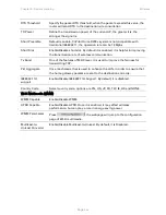
Page 83: ...in this range it will send a beacon frame for the information of the surrounding radio network Data Beacon Rate DTIM Specify the interval of transmitting the indication message it is a kind of cut dow...

Page 84: ...x Burst One of the features of MAC layer it is used to improve the fairness for transmitting TCP Pkt_Aggregate It is a mechanism that is used to enhance the LAN in order to ensure that the home gatewa...

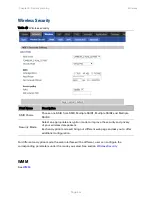
Page 85: ...Security Mode Select an appropriate encryption mode to improve the security and privacy of your wireless data packets Each encryption mode will bring out different web page and ask you to offer additi...

Page 86: ...Chapter 3 System planning Wireless Page 3 46 WDS See WDS WPS See WPS Station Info See Station Info Advanced See Advanced...

Page 87: ...Field Name Description SIP T1 The minimum scale of retransmission time Max Forward SIP contains Max Forward message header fields used to limit the requests for forwards SIP Reg User Agent Name The ag...

Page 88: ...to enable the call packet encryption function SRTP Prefer Encryption The preferred encryption type of calling packet the Message body of INVITE Message Service Type Choose the server type NAT Travers...

Page 89: ...eer To Peer Enable Disable PEER to PEER If enabled SIP 1 will not send register request to SIP server but in Status SIP Account Status webpage Status is Registered lines 1 can dial out but the externa...

Page 90: ...sword Enter SIP password provided by SIP Proxy Audio Configuration Table 50 Audio configuration Field Name Description Audio Codec Type1 Choose the audio codec type from G 711U G 711A G 722 G 729 G 72...

Page 91: ...sable T 38 Redundancy T 38 CNG Detect Enable Enable Disable T 38 CNG Detect gpmd attribute Enable Enable Disable gpmd attribute Supplementary Service Subscription Table 51 Supplementary service Field...

Page 92: ...vice DND Enable Disable DND do not disturb If enable any phone call cannot arrive at the device default is disable Speed Dial Enter the speed dial phone numbers Dial 74 to active speed dial function T...

Page 93: ...ou can use the default settings Refresher Choose refresher from UAC and UAS Prack Enable Enable Disable prack SIP OPTIONS Enable When you set enable the device will send SIP OPTION to the server inste...

Page 94: ...the user request URI check Only Recv request from server Enable Disable the only receive request from server Server Address The IP address of SIP server SIP Received Detection Enable Disable SIP Recei...

Page 95: ...x value of home gateway s jitter delay home gateway is an adaptive jitter mechanism Ringing Time How long CnPilot Home R200x will ring when there is an incoming call Ring Waveform Select regional ring...

Page 96: ...e will forward all calls to the phone number immediately when there is an incoming call Busy Forward The phone number which the calls will be forwarded to when line is busy No Answer Forward The phone...

Page 97: ...ion are ranged from R1 to R9 default value is R1 R key hold code Set the R key hold code options are ranged from R1 to R9 default value is R2 R key transfer code Set the R key transfer code options ar...

Page 98: ...ice Enable Disable CWCID If enable the device will display the waiting call s caller ID or it won t display Default is disable Dial Time Out How long cnPilot Home will sound dial out tone when cnPilot...

Page 99: ...e Digit Map Enter the sequence used to match input number The syntactic please refer to the following Dial Plan Syntactic Action Choose the dial plan mode from Deny and Dial Out Deny means CnPilot Hom...

Page 100: ...ameters Step 4 Press OK button to end configuration Dial Plan Syntactic Table 59 Dial Plan No String Description 1 0 1 2 3 4 5 6 7 8 9 Allowed characters 2 x Lowercase letter x stands for one legal ch...

Page 101: ...y Make outside dial tone after dialing x stop until dialing character y For example 9 1xxxxxxxxxx the device reports dial tone after inputting 9 stops tone until inputting 1 9 8 010x make outside dia...

Page 102: ...lick to select the blacklist file and click to upload it to CnPilot Home Click to save the blacklist file to your local computer Select one contact and click edit to change the information click delet...

Page 103: ...Chapter 3 System planning FXS1 Page 3 63 Call Log To view the call log information such as redial list incoming call answered call and missed call Table 61 Call log Redial List...

Page 104: ...Chapter 3 System planning FXS1 Page 3 64 Answered Calls Missed Calls...

Page 105: ...Chapter 3 System planning FXS2 Page 3 65 FXS2 The settings of FXS2 are the same as FXS1 See FXS1 on page 3 49...

Page 106: ...MAC addresses Mac address Add the Mac address filtering Dest IP address Destination IP address Source IP address Source IP address Protocol Select a protocol name support for TCP UDP and TCP UDP Dest...

Page 107: ...Chapter 3 System planning Security Page 3 67 Content Filtering Table 63 Content filtering...

Page 108: ...at already existed blacklist Delete Cancel You can choose to delete or cancel the existing filter rules Add a URL Filter Add URL filtering rules Add Cancel Click adds to add one rule or click cancel C...

Page 109: ...ver the connected device can automatically obtain DHCP and DNS services UPnP devices can be automatically added to the network without affecting previously connected devices Table 64 UPnP Field Name D...

Page 110: ...nning Application Page 3 70 Table 65 IGMP Field Name Description IGMP Proxy enable Enable Disable IGMP function MLD Table 66 MLD Field Name Description MLD enable Enable Disable MLD function Multicast...

Page 111: ...age the USB storage device Table 67 Disk Management Field Name Description Add Adding files to the USB storage device Delete Remove the USB storage device file Remove Disk Transfer files within a USB...

Page 112: ...FTP server port number Max Sessions Maximum number of connections Create Directory Enable Disable create directory Rename File Directory Enable Disable rename file directory Remove File Directory Ena...

Page 113: ...ame Description SAMBA Server Enable Disable SAMBA server Workgroup Enter the working group NetBIOS Name Network basic input output system name Add Add a shared file Edit Edit a shared file Del Delete...

Page 114: ...eb access system log and associated configuration TR069 Management Save config file Table 70 Save Config File Field Name Description Config file upload and download Upload click on browse select file...

Page 115: ...ic user New User Name You can modify the user name set up a new user name New Password Input the new password Confirm Password Input the new password again Language Select the language for the web the...

Page 116: ...ble remote telnet login Note Telnet access is disabled by default Telnet Port Set the port value which is used to telnet to the device NTP settings Table 72 NTP settings Field Name Description NTP Ena...

Page 117: ...Administration Page 3 77 Secondary NTP Server Options for NTP server s IP address or domain name NTP synchronization NTP synchronization cycle cycle time can be 1 to 1440 minutes in any one the defau...

Page 118: ...t in Month Start Day of Week Start Hour of Day analogously set stopping Month Week Day Hour in Stop Month Stop Day of Week Last in Month Stop Day of Week Stop Hour of Day Step 4 Press Saving button to...

Page 119: ...Level Select the system log there is INFO and Debug two grades the Debug INFO can provide more information Factory Defaults Setting Table 75 Factory Defaults Setting Description When enabled the devi...

Page 120: ...em planning Administration Page 3 80 Firmware Upgrade Table 77 Firmware upgrade Description 1 Choose upgrade file type from Image File and Dial Rule 2 Press Browse button to browser file 3 Press to st...

Page 121: ...er should have http server and upgrading file and configuring file Before testing or using HTTPS user should have https server and upgrading file and configuring file and CA Certificate file should sa...

Page 122: ...esync From SIP Enable Disable resync from SIP Option 66 It is used for In house provision mode only When use TFTP with option 66 to realize provisioning user must input right configuration file name i...

Page 123: ...ing SNMP traps Read Community Name String value that is used as a password to request information via SNMP from the device Write Community Name String value that is used as a password to write configu...

Page 124: ...It defines an application layer protocol for remote management of end user devices Using TR 069 the terminals establish connection with the Auto Configuration Servers ACS and get configured automatica...

Page 125: ...me used to connect the TR069 server to the DUT Password The password used to connect the TR069 server to the DUT Friendly Platform Operation Login Friendly Platform Enter the friendly server URL in th...

Page 126: ...Info menu item and you can see basic information about the test equipment As shown in Figure Button on the bottom of the device can perform basic operations such as reboot 3 If the device is properly...

Page 127: ...n the Advanced View menu button you can do some node As shown in Figure 1 Get AuthUserName of line1 Click on the top menu options and parameter values can be obtained depending on the options in the f...

Page 128: ...utton Edit can set new values for writable nodes After clicking edit fill in the new value directly in the box Parameter value field after the node name For example if set ProxyServer of Line1 the cur...

Page 129: ...System planning Administration Page 3 89 4 5 Firmware Upgrade Under is firmware upgrading operation on FreeACS 1 Equipment connection configure If the connection is successful you will see the follow...

Page 130: ...ration Page 3 90 2 Upload new firmware Choose File Script enter the appropriate documentation select the corresponding firmware click button of upload file to upload new firmware Uploaded firmware inf...

Page 131: ...t If the upgrade is successful you can check the firmware version number Here you can see the firmware has been updated to the required firmware version 5 TR 069 Profile Under nodes base on TR098 TR10...

Page 132: ...Password PeriodicInformEnable PeriodicInformInterval PeriodicInformTime ParameterKey ConnectionRequestURL ConnectionRequestUsername ConnectionRequestPassword UpgradesManaged UDPConnectionRequestAddre...

Page 133: ...etitions Timeout DataBlockSize DSCP SuccessCount FailureCount AverageResponseTime MinimumResponseTime MaximumResponseTime DownloadDiagnostics DiagnosticsState Interface DownloadURL DSCP EthernetPriori...

Page 134: ...EthernetPriority TestFileLength ROMTime BOMTime EOMTime TotalBytesSent TCPOpenRequestTime TCPOpenResponseTime Time NTPServer1 NTPServer2 UserInterface User 1 Enable RemoteAccessCapable X_WebPort X_We...

Page 135: ...sk GatewayIPAddress Interface ForwardingMetric LANConfigSecurity ConfigPassword LANDevice 1 LANEthernetInterfaceNumberOfEntries LANUSBInterfaceNumberOfEntries LANWLANConfigurationNumberOfEntries LANHo...

Page 136: ...eAddressingType LANEthernetInterfaceConfig 1 Enable Status MACAddress MACAddressControlEnabled MaxBitRate DuplexMode WLANConfiguration 1 Enable Status BSSID MaxBitRate Channel AutoChannelEnable SSID B...

Page 137: ...lDataTransmitRates PossibleDataTransmitRates RadioEnabled AutoRateFallBackEnabled TotalBytesSent TotalBytesReceived TotalPacketsSent TotalPacketsReceived TotalAssociations AssociatedDevice 1 Associate...

Page 138: ...rfaceConfig EnabledForInternet WANAccessType Layer1UpstreamMaxBitRate Layer1DownstreamMaxBitRate PhysicalLinkStatus TotalBytesSent TotalBytesReceived TotalPacketsSent TotalPacketsReceived WANConnectio...

Page 139: ...Allowed DNSServers MACAddress ConnectionTrigger RouteProtocolRx PortMappingNumberOfEntries PortMapping 1 PortMappingEnabled PortMappingLeaseDuration RemoteHost ExternalPort InternalPort PortMappingPro...

Page 140: ...led DNSOverrideAllowed DNSServers MACAddress TransportType PPPoEACName PPPoEServiceName ConnectionTrigger RouteProtocolRx PortMappingNumberOfEntries PortMapping 1 PortMappingEnabled PortMappingLeaseDu...

Page 141: ...pabilities MaxProfileCount MaxLineCount MaxSessionsPerLine MaxSessionCount SignalingProtocols Regions RTCP SRTP RTPRedundancy DSCPCoupled EthernetTaggingCoupled PSTNSoftSwitchOver FaxT38 FaxPassThroug...

Page 142: ...on VoiceProfile 1 Enable Reset NumberOfLines Name SignalingProtocol MaxSessions DTMFMethod DTMFMethodG711 SIP ProxyServer ProxyServerPort ProxyServerTransport RegistrarServer RegistrarServerPort Regis...

Page 143: ...TelephoneEventPayloadType Line 1 Enable Status CallState SIP AuthUserName AuthPassword URI Codec TransmitCodec ReceiveCodec TransmitBitRate ReceiveBitRate TransmitSilenceSuppression ReceiveSilenceSup...

Page 144: ...rt LocalUDPPort Stats ResetStatistics PacketsSent PacketsReceived BytesSent BytesReceived PacketsLost Overruns Underruns IncomingCallsReceived IncomingCallsAnswered IncomingCallsConnected IncomingCall...

Page 145: ...Chapter 3 System planning Administration Page 3 105 Diagnosis In this page user can do packet trace ping test and traceroute test to diagnose the device s connection status Table 82 Diagnosis...

Page 146: ...e Start button to start home gateway tracking and keep refreshing the page until the message trace shows to stop click the Save button to save captured packets 2 Ping Test Enter the destination IP or...

Page 147: ...Chapter 3 System planning Administration Page 3 107 Operating Mode Table 83 Operating mode Description Choose the Operation Mode as Basic Mode or Advanced Mode...

Page 148: ...m log Description If you enable the system log in Status syslog webpage you can view the system log in this webpage Logout Table 85 Logout Description Press the logout button to logout and then the lo...

Page 149: ...nt inventory management onboarding devices daily operations and maintenance cnMaestro offers full visibility across the entirety of a network This chapter covers Preparing the device Login to cnMaestr...

Page 150: ...llow the IP Addresses of the devices in the Firewall Server using an ACL Also enable the protocols like HTTP HTTPS and SSL This is required as the device communicates with the cnMaestro Server using w...

Page 151: ...mnetworks com 2 Sign in using your Cambium support center account credentials if you already have an Account or click the link Click Here to Register for the registration 3 After sign in create the co...

Page 152: ...n to cnMaestro Page 4 4 5 If the user has single company account he will be automatically redirected to that account after log in 6 If the user has multiple accounts once signed in the user needs to s...

Page 153: ...n home page 2 Provide the Serial number of the device in the combo box and click Claim Devices button 3 Serial Number can be found on the device enclosure and can be seen in the Device GUI Home page a...

Page 154: ...n cnMaestro page 2 Enter the Cambium ID and On Boarding key and click Save Reboot of the device is required in case of cnPilot R200 R201 devices 3 The Cambium ID and On Boarding key details are given...

Page 155: ...gure 5 Basic details Set Device Location The Location configuration page allows to configure device location in google map The device location can be configured Select the Network and Tower under whic...

Page 156: ...ows the current version if the device is claimed via Cambium ID User can upgrade later through Operate Software Update page Figure 7 Firmware update Configure Devices The Configure Devices page allows...

Page 157: ...Chapter 4 Managing device via cnMaestro Configuring the Devices Page 4 9 Figure 8 Configure devices...

Page 158: ...fig and software Images Updating After approval Current device is getting updated with the config and software Images On Boarded After approval Device is successfully on boarded 2 Once the device is i...

Page 159: ...e and click the Delete icon 2 Statistics collected from the time period when the device on boarded to the time it is being deleted are not deleted from the server In case if the user on boards the dev...

Page 160: ...1 Chapter 5 Troubleshooting Guide This chapter covers Configuring PC to get IP Address automatically Cannot connect to the Web GUI Forgotten Password Fast Bridge Setting cnMaestro On Boarding troubles...

Page 161: ...nnection that your PC uses select attribute and you can see the interface as shown in Figure 10 Step 4 Select Internet Protocol TCP IP click attribute button then click the Get IP address automaticall...

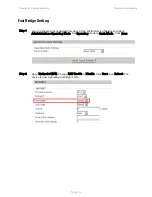
Page 162: ...cannot access the configuration web GUI Solution To factory default press and hold reset button for 10 seconds Fast Bridge Setting Description Step 1 Login Web GUI of the device Go to Administration O...

Page 163: ...Chapter 5 Troubleshooting Guide Configuring PC to get IP Address automatically Page 5 4 Step 3 Login from WAN port See example page Status Basic...

Page 164: ...D not configured Device is unclaimed Claim the device either by serial number or Cambium ID Device Not Claimed Device is not claimed Claim the device either by serial number or Cambium ID Connecting D...

Page 165: ...f it need not to be claimed This allows not to re enter serial number again and remove the invalid characters from entered serial number 3 cnMaestro Account ID is the Cambium ID or Account Name chosen...

Page 166: ...option 8 Go to Network tab and select INTERNET mode as DHCP STATIC or PPPoE based on the internet service provided by the ISP Most common mode of connection would be DHCP Please refer your ISP s instr...

Page 167: ...Protocol that enables a device to be assigned a new IP address and TCP IP parameters including a default gateway whenever the device reboots Thus DHCP reduces configuration time conserves IP addresse...

Page 168: ...number that identifies a network element by both network and host See also Subnet Mask IPv4 Traditional version of Internet Protocol which defines 32 bit fields for data transmission ISM Industrial Sc...

Page 169: ...col that is used to synchronize computer clock times in a network of computers PPPoE Point to Point Protocol over Ethernet Supported on SMs for operators who use PPPoE in other parts of their network...

Page 170: ...t that is associated with the physical address of another to pass data to only the intended recipient Compare to Bridge and Router TCP Alternatively known as Transmission Control Protocol or Transport...

Page 171: ...e Shared Key and also called WPA or WPA2 Personal it is a method of securing your network using WPA2 with the use of the optional Pre Shared Key PSK authentication which was designed for home users wi...

Reviews: