Page 14
Page 15
Once the lid or side panel are removed, access to the Service Area
has been gained. This access must be restricted to persons having
knowledge and practical experience of the appliance, in particular as
far as safety and hygiene are concerned.
De-scale
Note
: Whenever the body lid has been removed from the boiler a new lid
gasket will be required to ensure a steam-tight joint. Damage to the unit
caused by a poor lid seal is not covered under the warranty of the unit.
Scale deposits should be removed from all internal surfaces, particularly
the heating element and thermistor’s, by gently tapping or scraping. If
the deposits are soft, use a nylon pad and flush out. Abrasive cleaning
materials containing scouring powders and detergents must not be used,
such materials can cause taste problems. Chemical de-scalants must only
be used in accordance with the manufacturer’s instructions.
Basic operation
The water-fill and heat functions of the CB boiler are completely
independent of each other.
Heater function
The printed circuit board (PCB) controls the heating function of the boiler
by monitoring the top and bottom thermistors, the safety cutout and
the economy switch. The function of this switch is to bring the bottom
thermistor in or out of circuit. In the ‘ECON’ position, the bottom thermistor
is ignored resulting in a reduced volume of water being maintained
at operating temperature. In the ‘MAX’ position, both thermistors are
monitored and a larger volume of hot water is available for use at any one
time. The PCB also controls the external light unit to indicate when the
water is at the correct temperature: green for ready (i.e. top thermistor
satisfied), red for wait (i.e. water below temperature). If both lights are
displayed together, the low water safety cutout has tripped, or some
section of its circuit has become open. This would occur either because
the machine has been switched on without first allowing it to fill with
water, (and the element has energised in air), the safety cutout is faulty
(and should be replaced), or there is a poor contact at the PCB connector
pins. Removing and re-fitting the connector usually remedies the latter
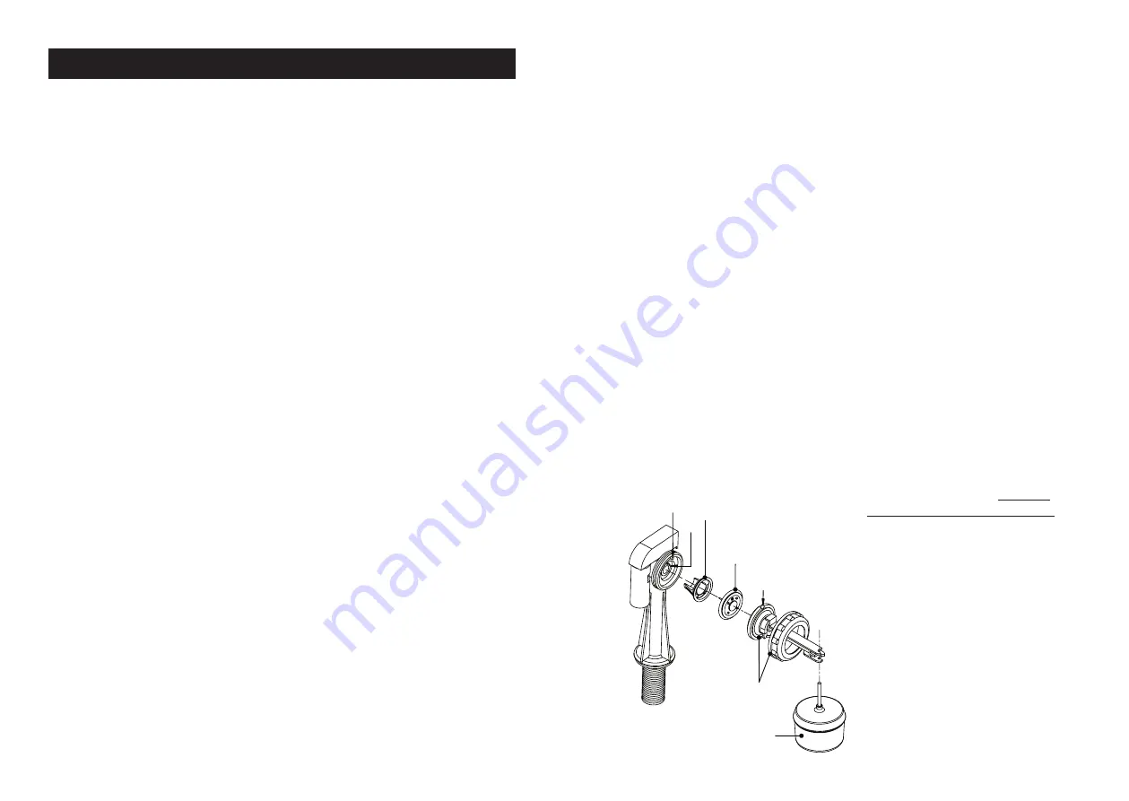
Diaphragm (FVD)
Central pin pointing
towards valve body
Filter (FVF)
Cutout
Locating boss
(FVAFC)
Float (FVFL)
Pin
Float arm
& cap
fault. The possibility also exists that the setting of the cutout has been
turned down. These are factory set to 120°C, but turning it down below
100°C would cause it to constantly trip. The red LED on the PCB will
flash when first energised indicating program initialisation. There after
the LED indicates ‘Neutral’ switched to element. Note: the element has a
permanent ‘Live’ feed.
Should an element fail and need to be replaced, it is necessary to replace
the four-piece lid gasket to ensure a reliable steam-seal.
In the event of a PCB failing and a replacement being required, full
instructions will be supplied. It is important to note, however, that the
integral Triac must be securely mounted against the copper heat-sink /
mounting bracket to ensure reliable heat dissipation.
Water-fill function
A Torbeck float valve controls the water level in the cold water tank, which
feeds the main boiling chamber (referred to as the ‘body’). This is generally
a reliable component, but problems can arise if the incoming water supply
contains debris. Occasionally, dirt can pass through the internal filter and
become lodged on the diaphragm, causing the valve to weep. This can
be remedied by dismantling the valve (as shown opposite) and gently
cleaning the diaphragm with fresh water. When re-assembling the valve,
the diaphragm must be re inserted with its central pin facing into the body
of the valve and with the pin on the body passing through the hole in the
diaphragm. Before tightening the nut, ensure that the cut-out in the float
arm is positioned around the locating boss on the valve body. The nut
should be hand-tightened only.
Note: The valve can take up to
15 seconds to fully close after
the float arm is raised. This is
a normal feature of the valve
and is intended to reduce the
effects of water / pipe hammer
For assistance with any aspect of
the machine, please call Calomax
directly on 0113 249 6681 or
e-mail [email protected]
SERVICE INSTRUCTIONS


