Page 4
Page 5
LOCATION
To comply with recommendations from the
health and safety executive it is important
that due consideration be given to safe
operation of the controls of the boiler. The
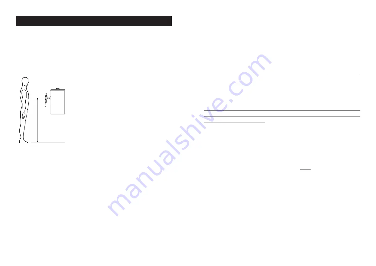
boiler should therefore be mounted in such a
manner that the operator can stand directly
facing the machine with the controls at a
recommended height from the floor to the
draw-off tap handle of /- 100mm.
Consideration should also be given to the
servicing requirements of the machine.
The maximum and minimum ambient
operating conditions must be between 5 °C
and 35 °C. The appliance is not suitable for
installation where a water jet could be used. Install the boiler in a position
having adequate ventilation, on a level and firm surface suitable for near
boiling temperatures. Allow clearance for the easy removal of the outer
casing lid and left hand side panel.
Start the installation
Unscrew the chromed lid vent and remove the outer casing lid. Remove
the left hand side outer casing panel to make connections. Holes are
provided in the boiler base for fastening down. Use M5 bolts and nuts.
New boiler outer-casings have a protective vinyl coating, which is easier to
remove when warm after commissioning, but make sure access will still be
available to do this before fixing the boiler.
COLD WATER INLET
In hard water districts the use of a Dosaphos Scale Reducer (obtainable
from Calomax Limited), for the alleviation of scale is recommended. (See
Accessories - Page 13).
The boiler must be connected to a suitable potable water supply in a
manner which complies with UK water regulations. The boiler should
be connected to a ½” (15mm) drinking water supply within a constant
pressure range from 20 KPa to 1000 KPa (0.2 to 10 Bar), via an isolating
stop cock fitted near the boiler
.
The boiler is supplied with ‘High Pressure’
and ‘Low Pressure restrictors. It is the responsibility of the Installation
Engineer to select the appropriate restrictor and fit it to the float valve
in accordance with the instruction sheet provided. Correct selection of
restrictor can significantly reduce noise associated with Water Hammer
/ Pipe Hammer. Note: HP restrictor is factory fitted.
BEFORE CONNECTING, THE SUPPLY PIPE MUST BE THOROUGHLY
FLUSHED OUT TO ENSURE THAT FOREIGN MATTER DOES NOT
BLOCK THE FLOAT VALVE
If the water supply contains excessive solids in suspension it is
recommended that a fine mesh “in line” water filter is fitted in the pipe
work after the stop cock.
When tightening the union connection to the float valve, hold the float
valve body to prevent it turning inside the tank and disturbing the
joint in the tank bottom. Jointing paste must
NOT
be used as this will
corrode the plastic threads of the valve.
Check that the float valve operates correctly whilst initially filling the
boiler and ensure that it cuts off at the level indicator. The float must
not foul against the side of the tank.
For further details see Service
Instructions. Note: The valve is ‘slow closing’ and so may take
upto 15 seconds to close fully when the float arm is raised to the
horizontal position.
IMPORTANT Ensure cold water can be drawn from the draw off tap
before switching on the electricity supply. (The electric supply to the
boiler must always be turned off before the water supply).
A suitably qualified engineer must install this unit. Plumbing and
electrical installation work is involved.
INSTALLATION
The appliance must at least be installed in a location where it can
be overseen by trained personnel, but may be installed in a location
where its use and servicing is restricted to trained personnel


