


DIGITAL COMMUNICATION AND CONFIGURATION
A choice of two digital communication interfaces is available.
For temporary connection, configuration of the sensor, and diagnostics, we suggest the USB
adapter, model LCT.
For continuous digital communications, configuration and data acquisition, we suggest the
RS-485 Modbus network interface, model LCT-485.
The LCT and LCT-485 are not certified for use in hazardous areas. They
must only be connected on the safe side of the safety isolator.
USB
All models are configurable via the optional USB adapter (Loop Configuration Tool, model LCT)
and free CalexConfig configuration software.
The LCT has hook-type connectors and may be connected to the 4-20 mA loop as shown
above.
For information about installing and using the LCT, see the
Loop Configuration Tool (LCT)
section of this manual.
RS-485 MODBUS
The optional LCT-485 Network Interface (not shown) allows an ExTemp sensor to be
connected to an RS-485 Modbus RTU network for temperature measurement,
configuration and data acquisition.
Each LCT-485 unit provides connectivity for one sensor, and multiple LCT-485 units
can be connected to a single Modbus network.
See the ExTemp data sheet and LCT-485 Operator’s Guide for more information.
OUTPUT CABLE INSTALLATION
The recommended output cable type is LAPP ÖLFLEX EB CY 2x0.75mm². An alternative cable
may be used. See the ExTempMini Guide to Certification and Installation for full details.
GROUNDING
The main enclosure
must
be connected to earth using the provided earth terminal. The
output cable shield must be terminated to the enclosure as per the above instructions, and
the cable shield
must not
be connected to earth at the other end.
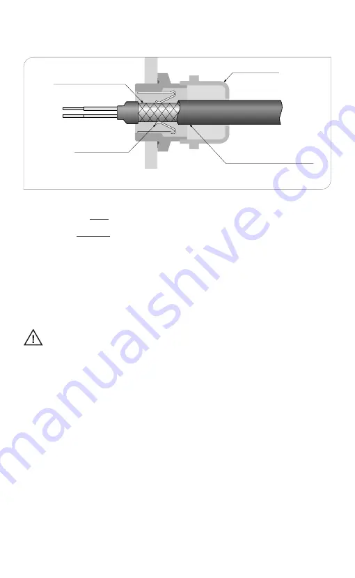
Spring contacts
Cable gland
Output cable e.g. Lapp
ÖLFLEX EB CY 2x0.75mm²
Ensure the metal spring contacts in the cable gland are touching the cable shield braid.
Cable shield braid
11


