background image

Bag 2

4-40 x 5/16”

FH steel

4-40 x ½”

FH Alum

One-Piece

Side Links

Red Low-

Profile Ball

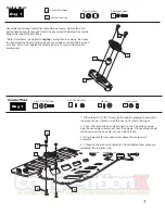
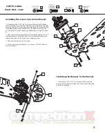
1 - In Bag 2, find the graphite bottom plate [10].
Secure it to the center pivot assembly with the
½” red flat head screw [11]. Secure it tight with
the red 7/8” hex standoff [15].

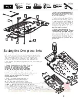
2 - Find the 4 red low profile balls [12]. Secure
them as shown with the steel 5/16” screws [13].

3 - Locate the plastic side links [14]. Inspect the
links and you will notice that the screw holes on
one side of the link are larger than the holes on
the other side. Before popping the links on the
balls [12], be sure that the larger hole faces
toward the outside of the chassis.

4 - Slide the 2-56 button head screws [4]
through the large holes in the outside of the side
links, and then thread them into the small inner
holes as shown in the illustration. Do not tighten
these screws down all the way. Put just enough
tension on them so that there is no play in the
links, but so they pivot freely on the balls. The
car will NOT handle properly if the links are too
tight on the balls.

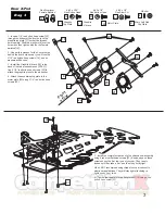
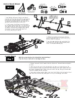
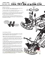
1 - Be sure the 2 aluminum locknuts on top of the center pivot are slightly loose.
There should be a washer under each alum locknut. Notice that the center pivot
“floats" or moves slightly on the 2 screws. This "floating" allows the links
to "free up". This ensures that the rear pod plate pivots freely on the links
and center pivot ball. This is a crucial step when setting up the Battle Axe.

2 - Snap the 2 links on the balls (done in previous step). They should rock freely on
the pivot balls.

3 - Place the chassis/backplate on a flat surface. No tires and
no diff on the car! A smooth table or desk should do. Be
sure that the rear bottom plate and chassis are in a
straight line, flat against the table, again, no tires on the
car. Lightly “tap” the chassis and rear pod releasing any
tension in the links. Keep the chassis flat on the table for step 4.

4 - Hold the chassis at the hold point “H”

by pressing

the chassis down to the table. Slowly tighten the 2 locknuts that
secure the center pivot assembly. For now, just lightly
snug one side then the other.

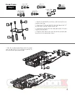
5 - Pick up the car and check the pivoting action of
rear lower plate. Rotate the rear plate from side-to-
side. It should move free without binding or "clicking".
If it does not, loosen the pivot locknuts and repeat steps 3+4.

If it rotates smoothly, tighten the locknuts on the center pivot more
securely. Do this by again holding the chassis down to the table at the
hold point “H”. Slowly and carefully, fully tighten the locknuts that hold the center pivot
assembly to the chassis. The handling of the Battle Axe hinges (pun intended!) on the
free movement of this rear plate. Be sure that the rear links and rear plate are free and not binding.

(not the rear pod)

Setting the One-piece links

2

Red 7/8”

Standoff

15

15

10

11

12

14

13

11

12

13

14

Rotate

Center Pivot

H

2-56 Button Head

4

4

Summary of Contents for Battle Axe 2.0

Page 1: ...tle Axe 2 0 T Q s W ins 2009 Snowbirds Calandra Racing Concepts 6785 Martin Street Rome NY 13440 Tel Fax 315 338 0867 www teamcrc com servo and saver not included 1 10th Oval Weapon from Team CRC Part...

Page 2: ...screws too much or you could warp the pivot socket slightly Red Locknut 1 Place the 4 40 x 7 16 screws 5 through the graphite chassis 6 in the holes shown Tighten a 4 40 thin hex nut 7 down fairly tig...

Page 3: ...the links and center pivot ball This is a crucial step when setting up the Battle Axe 2 Snap the 2 links on the balls done in previous step They should rock freely on the pivot balls 3 Place the chas...

Page 4: ...4 1 4 red button head screws 22 to attach the graphite piece to the aluminum 4 Attach the assembled top plate to the motor plate 20 using 2 1 4 red button head screws 22 Rear X Pod 3 16 17 20 16 17 19...

Page 5: ...the 3 16 button head 16 in the hole shown 4 Repeat the above steps for the second Tweak Plate but flip the plate first as this is for the opposite side of the car Tweak Plates 4 24 24 16 15 22 18 Red...

Page 6: ...the oil to bleed out tightening and loosening the delrin insert while keeping the shaft fully depressed inside the body This will bleed the shock 7 When the shock is fully bled no oil will leak and th...

Page 7: ...nt to the chassis 6 using two 4 40 x 1 4 red FH screws 23 in the holes shown in the diagram 2 Insert the antenna tube into the vertical hole in the center shock mount and then tighten the clamp with a...

Page 8: ...rner entry 2 With side cutters or good scissors cut off do NOT break off the 3 4 and 5 mm spacers 35 from the ride height tree Use the 5 mm thickness for 1 10th scale tires For fine front ride height...

Page 9: ...nd slide it through the lower arm pivot ball 30 then thread it into the steering block with the steering block all the way down against the pivot ball Thread the king pin in until the spring just touc...

Page 10: ...ecure the front end assembly to the plate using the 8 32 x low head front end screws 55 Again we recommend starting in the middle hole giving you the option to go longer or shorter 3 Repeat these step...

Page 11: ...ervo saver from the front and then secure them with a red locknut 9 on the back Mount the servo saver to the servo 2 Slide a washer 8 over each of the 4 40 x 3 8 red cap head screws 60 Now slide the s...

Page 12: ...plain bearing 74 over the end of the axle Align the diff ring so that it notches into the axle flange Place the assembled gear with the greased diff balls over the axle and push it down over the plai...

Page 13: ...k the collar with the set screw 12 82 60 Adjust body height by raising or lowering this collar 79 81 83 80 82 M3 x 8mm Steel Button Head 80 Two rear body mount locations Bag 11 4 40 x 3 8 Red Socket C...

Page 14: ......

Page 15: ......

Page 16: ...Length Lube Upper Arm Length Upper Arm Height Ackerman LR Width from center RR Width from center Tires RF Tire Compound RR Tire Compound LF Tire Size LF Additive LF Glue LR Tire Size LR Additive LR G...

Reviews: