background image

14

31-2000647   Rev.2

Instrucciones de Instalación

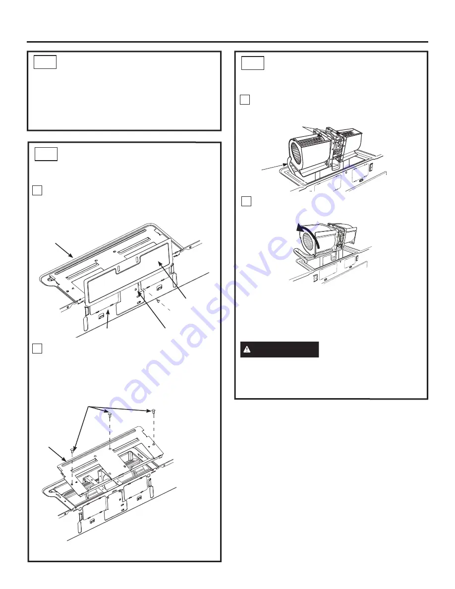
CONTROLE LA ORIENTACIÓN DEL 
MOTOR DEL SOPLADOR 

ADAPTACIÓN DEL SOPLADOR DEL 
HORNO MICROONDAS PARA LA 

RECIRCULACIÓN 

ADAPTACIÓN DEL SOPLADOR 
DEL HORNO MICROONDAS 
PARA LA RECIRCULACIÓN 

A3

A4

A4

La abertura de las paletas del ventilador del soplador 

deberán estar enfrentadas con la cara frontal del horno 

microondas. Si la abertura del ventilador ya enfrenta 

la parte frontal del horno microondas, vaya al Paso 

A5. De otro modo, vaya al Paso A4 para ajustar la 

orientación del soplador. 

Nota: 

Asegúrese de que los cables permanezcan 

dirigidos hacia las aberturas de la estructura del 

motor. Para evitar daños sobre el cableado del motor 

del ventilador, inserte el motor cuidadosamente de 

forma tal que el cableado del motor del ventilador no 

tenga contacto con el soporte del cable de encendido 

del microondas.

Con cuidado empuje hacia usted la unidad del 

calentador. Los cables se extenderán lo suficiente 

como para permitirle ajustar la unidad del calentador.

Haga rodar el calentador de modo que las aberturas de 

las paletas del ventilador enfrenten la parte superior del 

horno. Vuelva a colocar el calentador en la abertura. 

3

4

Parte Trasera 
del Microondas

Gire 90º

Parte 

Trasera del 

Microondas

Paletas del  
Ventilador

Cables

Riesgo de Descarga 

Eléctrica. Puede ocasionar 

lesiones o la muerte. No empuje ni extienda el 

cableado de la unidad del soplador.  Asegúrese de 

que los cables no posean cortes.

ADVERTENCIA

Retire el tornillo que sostiene la tapa del soplador 

y retire la tapa del soplador de la placa trasera 

del horno microondas, deslizando la misma hacia 

arriba. 

Retire los tornillos que aseguran la placa del 

soplador y retire la placa del soplador de la caja 

externa, deslizando la misma hacia la parte trasera 

del horno microondas y empujando hacia arriba. 

1

2

Blower Plate

Blower Cover

Blower Cover
Screw

Back of Microwave

Blower Plate

Blower Plate Screws

Summary of Contents for CVM919

Page 1: ...ure to leave these instructions with the consumer BEFORE YOU BEGIN Note to Consumer Keep these instructions for future reference Skill level Installation of this appliance requires basic mechanical and electrical skills Proper installation is the responsibility of the installer Product failure due to improper installation is not covered under the warranty Over the Range Microwave Oven CVM721 CVM91...

Page 2: ...nting Space 8 Step by step installation guide Placement of Mounting Plate 9 11 Removing the Mounting Plate 9 Finding the Wall Studs 9 Determining Mounting Plate Location 10 Aligning the Mounting Plate 11 Installation Types 12 23 Recirculating 13 16 Attach Mounting Plate to Wall 13 Preparation of Top Cabinet 13 Adjust the Blower 14 Installing the Charcoal Filter 15 Mount the Microwave Oven 15 16 In...

Page 3: ...a peninsula It must be mounted to BOTH a top cabinet AND a wall To avoid the risk of personal injury back injury or other injuries due to excessive weight of the microwave oven or property damage you will need two people to install this microwave oven This is the safety alert symbol This symbol alerts you to potential hazards that can kill or hurt you and others All safety messages will follow the...

Page 4: ...onal Tin snips for cutting damper if required Electric drill with 3 16s 7 16s 1 2s and 5 8s drill bits Hammer optional Stud finder Filler blocks or scrap wood pieces if needed for top cabinet spacing used on recessed bottom cabinet installations only Gloves Saw saber hole or keyhole Level Duct and masking tape Scissors to cut template if necessary Safety goggles ...

Page 5: ...l have to be cut to fit using the tin snips in order to allow free movement of the damper The following chart describes an example of one possible ductwork installation OUTSIDE BACK EXHAUST EXAMPLE ONLY EQUIVALENT NUMBER DUCT PIECES LENGTH x USED LENGTH Roof Cap 24 Ft x 1 24 Ft 12 Ft Straight Duct 12 Ft x 1 12 Ft 6s Round Rectangular to Round 5 Ft x 1 5 Ft Transition Adaptor Equivalent lengths of ...

Page 6: ... It is important that venting be installed using the most direct route and with as few elbows as possible This ensures clear venting of exhaust and helps prevent blockages Also make sure dampers swing freely and nothing is blocking the ducts Exhaust connection The hood exhaust has been designed to mate with a standard 31 4Ǝ Ǝ UHFWDQJXODU GXFW If a round duct is required a rectangular to round tran...

Page 7: ...TALLATION INSTRUCTIONS QUICK USE CARE ADDITIONAL PARTS PARTS INCLUDED You will find the installation hardware contained in a packet with the unit Check to make sure you have all these parts NOTE Some extra parts are included HARDWARE PACKET DAMAGE SHIPMENT INSTALLATION If the unit is damaged in shipment return the unit to the store in which it was bought for repair or replacement If the unit is da...

Page 8: ...he oven beneath smooth flat cabinets be careful to follow the instructions on the top cabinet template for power cord clearance 13 max for standard installation 15 cabinet depth requires additional steps using an additional installation kit JX15BUMPWW BB For models with top venting holes Do not allow cabinetry or other objects to block the airflow of the vent Backsplash Ǝ RU PRUH from the floor to...

Page 9: ...ble installation instructions filters exhaust adaptor damper shelf and the small hardware bag Do not remove the foam packing protecting the front of the oven Fold back all 4 carton flaps fully against carton sides Then carefully roll the oven and carton over onto the top side The oven should be resting in the foam packing REMOVING THE OVEN FROM THE CARTON REMOVING THE MOUNTING PLATE FINDING THE WA...

Page 10: ...e the inside depth of the front overhang Draw a horizontal line on the back wall an equal distance below the cabinet bottom as the inside depth of the front overhang For this type of installation with front overhang align the mounting tabs with this horizontal line not touching the cabinet bottom as described in Step D Plate Position flat bottom cabinet Plate Position cabinet with front overhang M...

Page 11: ...must be used for mounting NOTE Holes C and D are inside area E If neither C nor D is in a stud find a stud somewhere in area E and draw a fifth circle to line up with the stud It is important to use at least one wood screw mounted firmly in a stud to support the weight of the microwave oven Set the mounting plate aside WARNING Risk of electric shock Can cause injury or death Take care to not drill...

Page 12: ... of ventilation required for your installation and proceed to that section B OUTSIDE TOP EXHAUST VERTICAL DUCT See page 17 Adaptor in Place for Outside Top Exhaust 2 OUTSIDE BACK EXHAUST HORIZONTAL DUCT See page 21 C RECIRCULATING NON VENTED DUCTLESS See page 13 A Charcoal Filter Accessory Kit is required for the non vented exhaust See your Owner s Manual for the kit number A Installation Instruct...

Page 13: ... toggle wings into the holes in the wall to mount the plate NOTE Before tightening toggle bolts and wood screw make sure the tabs on the mounting plate touch the bottom of the cabinet or the horizontal level line when pushed flush against the wall and that the plate is properly centered under the cabinet CAUTION Be careful to avoid pinching fingers between the back of the mounting plate and the wa...

Page 14: ...ding it toward the back of the microwave and pulling it up NOTE Make sure the wires remain routed through the openings in the motor frame To avoid damage to the fan motor wiring insert motor carefully such that the fan motor wiring does not contact the microwave power cord bracket Carefully pull out the blower unit The wires will extend far enough to allow you to adjust the blower unit Roll the bl...

Page 15: ...til it restes in place behind the tab Close the charcoal filter cover Close the door 2 1 3 4 5 Filter Bottom Tab ADAPTING MICROWAVE BLOWER FOR RECIRCULATION A4 Slide the blower plate back onto the microwave by placing the side tabs into the slots and pushing gently until the back tab is seated into the rear slot replace the 3 blower plate screws Replace the blower motor screw Slide the Blower cove...

Page 16: ...p cabinet Keep it tight throughout Steps 1 3 Do not pinch cord or lift microwave oven by pulling cord Lift microwave tilt it forward and hook slots at back bottom edge onto four lower tabs of mounting plate Rotate front of microwave oven up against cabinet bottom 1 2 Power Cord A6 MOUNT THE MICROWAVE OVEN cont 5 4 Tighten the three screws to the top of the microwave oven While tightening screws ho...

Page 17: ...O THE WALL B1 Attach the plate to the wall using toggle bolts At least one wood screw must be used to attach the plate to a wall stud Recommended locations on the mounting plate are indicated by A B C and D Remove the toggle wings from the bolts Insert the bolts into the mounting plate through the holes designated to go into drywall and reattach the toggle wings to 3 4s onto each bolt 1 INSTALLATI...

Page 18: ...ue to Step B4 to adjust the blower orientation Under the condition of the blower cover is installed on the top of the microwave remove the screw holding the blower cover and remove the blower cover from the blower plate by sliding it right Carefully pull out the blower unit The wires will extend far enough to allow you to adjust the blower unit Remove the 3 screws securing the blower plate and rem...

Page 19: ...crowave oven You will need to make adjustments to assure proper alignment with your house exhaust duct after the microwave oven is installed Position the blower plate with damper back on the microwave and secure it with the screws that were removed 1 2 3 4 5 5 6 ADAPTING BLOWER FOR OUTSIDE VENTILATION B4 Slide the blower plate back onto the microwave by placing the side tabs into the slots and pus...

Page 20: ...ct tape House Duct Self Aligning Screw MOUNT THE MICROWAVE OVEN cont B6 B7 This distance can NOT exceed 2 to ensure proper installation MOUNT THE MICROWAVE OVEN B6 CAUTION To avoid the risk of personal injury back injury or other injuries due to excessive weight of the microwave or property damage you will need two people to install this microwave IMPORTANT Do not grip or use handle during install...

Page 21: ...r outside exhaust Read the instructions on the REAR WALL TEMPLATE Tape it to the rear wall lining up with the holes previously drilled for holes A and B in the mounting plate Cut the opening following the instructions of the REAR WALL TEMPLATE Wall Mounting Plate Spacing for Toggles More Than Wall Thickness Toggle Bolt Toggle Wings To use toggle bolts Bolt End Place the mounting plate against the ...

Page 22: ... Remove the screw holding the blower cover and remove the blower cover from the back plate of microwave by sliding it up Remove the screws securing the blower plate and then remove the blower plate from the outer case by sliding it toward the back of the microwave and pulling up C4 1 2 4 The fan needs to be turned 180 degrees to the right to be in the correct orientation keeping the blower part of...

Page 23: ... the unit with the hinge at the top 7 6 8 ADAPTING BLOWER FOR OUTSIDE BACK EXHAUST cont C4 5 Roll the blower unit 90 so that fan blade openings are facing out the back of the microwave and gently place the fan back into the cavity NOTE Make sure the wires remain routed through the openings in the motor frame To avoid damage to the fan motor wiring insert motor carefully such that the fan motor wir...

Page 24: ...ew This distance can NOT exceed 2 to ensure proper installation 3 MOUNT THE MICROWAVE OVEN C5 CAUTION To avoid the risk of personal injury back injury or other injuries due to excessive weight of the microwave or property damage you will need two people to install this microwave IMPORTANT Do not grip or use handle during installation WARNING Risk of Electric Shock Can cause injury or death If inst...

Page 25: ...l from the microwave oven 2 Make sure the microwave oven has been installed according to instructions 1 BEFORE YOU USE YOUR MICROWAVE OVEN Ensure proper ground exists before use QUICK USE CARE Installation Instructions Install turntable and turntable ring in cavity 3 5 Where a standard two prong wall receptacle is encountered it is very important to have it replaced with a properly grounded three ...

Page 26: ...26 31 2000647 Rev 2 Installation Instructions Printed in China ...

Page 27: ...es la Consumidor ANTES DE COMENZAR Nota para el Comprador Conserve estas instrucciones para referencia futura Nivel de habilidad La instalación de este electrodoméstico requiere un nivel básico de habilidades mecánicas y eléctricas La correcta instalación del producto es responsabilidad del instalador Si se producen fallas en el producto debido a una instalación inadecuada la Garantía no cubrirá l...

Page 28: ...uía de instalación paso a paso Colocación de la Placa de Montaje 9 10 Retiro de la Placa de Montaje 9 Búsqueda de los Montajes de Pared 9 Determinación de la Placa de Montaje 10 Alineación de la Placa de Montaje 11 Tipos de Instalación 12 23 Recirculación 13 16 Adjunte la Placa de Montaje a la Pared 13 Preparación del Gabinete Superior 13 Ajuste el Calentador 14 Cómo Instalar el Filtro de Carbón 1...

Page 29: ... 20 amperios La caja del tomacorriente deberá estar localizada en el gabinete encima del horno La caja del tomacorriente debe ser instalada por un electricista calificado y debe conformarse al National Electrical Code o al código local en efecto Asegúrese de contar con una conexión a tierra adecuada antes de usar ADVERTENCIA Riesgo de Descarga Eléctrica Puede ocasionar lesiones o la muerte NUNCA b...

Page 30: ... requiere Taladro eléctrico con brocas de 3 15 7 16 1 2 y 5 8 Martillo opcional Detector de montantes Bloques de llenado o piezas de fragmentos de madera si son necesarios para para generar espacio en el gabinete superior usados en instalaciones de gabinetes inferiores ahuecados únicamente Guantes Sierra sable agujero o cerradura Nivel Cinta para conductos y de mascarar Tijeras para cortar plantil...

Page 31: ...ape posterior se debe tener cuidado al alinear el escape entre los espacios de los postes de viga de la pared o la pared debería ser preparada en el momento de su construcción dejando suficiente espacio entre los postes de viga de la pared para acomodar el escape IMPORTANTE Si se usa un adaptador de transición de rectángulo a redondo las esquinas del fondo del regulador de tiros deberán cortarse p...

Page 32: ... de diámetro Longitud máxima del conducto Para lograr un movimiento satisfactorio del aire la longitud total del conducto rectangular de 31 4Ǝ Ǝ R HO FRQGXFWR UHGRQGR GH Ǝ GH GLiPHWUR no debe sobrepasar 140 pies equivalentes Los codos transiciones paredes y tapas de techo etc presentan resistencia adicional al flujo de aire y son equivalentes a una sección de conducto recto el cual es más largo qu...

Page 33: ...ástico 1 Instrucciones de Instalación Si la unidad se daña durante el envío devuelva la unidad a la tienda donde fue comprada para su reparación o reemplazo Si la unidad es dañada por el cliente la reparación o reemplazo es responsabilidad del cliente Si la unidad es dañada por el instalador si no es el cliente la reparación o reemplazo deberá ser realizado por arreglo entre el cliente y el instal...

Page 34: ...orno debajo de gabinetes de fondos lisos y planos tenga cuidado de seguir cuidadosamente las instrucciones en la plantilla del gabinete superior para el espacio de tolerancia del cable eléctrico Máx de 13 para una instalación estándar una profundidad del gabinete de 15 requiere pasos adicionales utilizando el kit de instalación adicional JX15BUMPWW BB Para modelos con hoyos de ventilación superior...

Page 35: ...ación los filtros el adaptador de escape el regulador de tiro estante y la pequeña bolsa con los elementos de instalación No remueva la espuma de poliestireno que protege el frente del horno Pliegue hacia atrás las alas de la caja Luego cuidadosamente ruede el horno hasta que quede apoyado sobre la parte superior El horno deberá descansar sobre la espuma de poliestireno CÓMO REMOVER EL HORNO DEL E...

Page 36: ...je una línea horizontal en la pared trasera que posea la misma distancia debajo del fondo del gabinete como de la profunidad interior del frente saliente Para este tipo de instalación con frente saliente alinee las lengüetas montantes con la línea horizontal sin tocar la parte inferior del gabinete como se describe en el paso D Posición de la Placa gabinete inferior plano Posición de la Placa gabi...

Page 37: ...ro del área E Si C y D no están en un montaje busque un montaje en alguna parte en el área E y dibuje un quinto círculo que se alinee con el montaje Es importante usar por lo menos un tornillo de madera montado de manera firme en un montaje para sostener el peso del horno microondas Deje la placa de montaje a un costado ADVERTENCIA Riesgo de Descarga Eléctrica Puede ocasionar lesiones o la muerte ...

Page 38: ...ra su instalación y proceda a dicha sección B ESCAPE EXTERIOR SUPERIOR CONDUCTO VERTICAL Lea la Página 17 El Adaptador Está en el Lugar Correcto para el Escape Exterior Superior 2 ESCAPE EXTERIOR TRASERO CONDUCTO HORIZONTAL Lea la Página 21 C RECIRCULACIÓN SIN CONDUCTOS NO VENTILADOS Lea la Página 13 6H UHTXLHUH XQ LW GH FFHVRULRV GH LOWURV GH DUEyQ SDUD el escape no ventilado Consulte el número d...

Page 39: ...tra la pared e inserte las tuercas mariposa en los agujeros de la pared para montar la placa NOTA Antes de ajustar los tornillos con resorte y el tornillo de madera asegúrese de que las lengüetas sobre la placa de montaje toquen la parte inferior del gabinete o la línea a nivel horizontal cuando se lo presione contra la pared y que la placa esté correctamente centrada debajo del gabinete PRECAUCIÓ...

Page 40: ...Con cuidado empuje hacia usted la unidad del calentador Los cables se extenderán lo suficiente como para permitirle ajustar la unidad del calentador Haga rodar el calentador de modo que las aberturas de las paletas del ventilador enfrenten la parte superior del horno Vuelva a colocar el calentador en la abertura 3 4 Parte Trasera del Microondas Gire 90º Parte Trasera del Microondas Paletas del Ven...

Page 41: ... hasta que esté correctamente colocada detrás de la lengüeta Cierre la tapa del filtro de carbón Cierre la puerta 2 1 3 4 5 Filtro Parte Inferior del Lengüeta Deslice la placa del soplador nuevamente hacia el horno microondas colocando las lengüetas laterales en las ranuras y empujando suavemente hasta que la lengüeta trasera quede ubicada en la ranura trasera reemplace los 3 tornillos de la placa...

Page 42: ...orno microondas o daños sobre la propiedad deberá contar con la ayuda de dos personas para instalar este horno microondas IMPORTANTE No tome ni use la manija durante la instalación ADVERTENCIA Riesgo de Descarga Eléctrica Puede ocasionar lesiones o la muerte Si instala la unidad con encimeros de metal cubra el agujero del extremo del cable de suministro de corriente con aislante para el cable del ...

Page 43: ...a placa a la pared usando tornillos con resortes Por lo menos un tornillo de madera deberá ser usado para adherir la placa al montaje de pared Las ubicaciones recomendadas sobre la placa de pared están indicadas por A B C y D Retire las tuercas mariposa de los tornillos Inserte los tornillos en la placa de montaje a través de los agujeros designados para entrar en la placa de yeso y vuelva a ajust...

Page 44: ...el soplador se encuentre instalada en la parte superior del horno microondas retire el tornillo que sostiene la tapa del soplador y retire la tapa del soplador de la placa del soplador deslizando la misma hacia la derecha Retire los 3 tornillos que aseguran la placa del soplador y retire la placa del soplador de la caja externa deslizando la misma hacia la parte trasera del horno microondas y empu...

Page 45: ... la unidad hacia arriba y el frente hacia usted Deslice el regulador de izquierda a derecha dentro de las lengüetas en el plato calentador La cinta amarilla del regulador deberá estar en dirección contraria hacia usted Retire la cinta amarilla del regulador Asegúrese de que el regulador gire fácilmente antes del montar el horno microondas Deberá hacer ajustes para asegurar una alineación correcta ...

Page 46: ...a distancia NO puede superar las 2 para asegurar una instalación adecuada Frente del Gabinete MONTE EL HORNO MICROONDAS B6 PRECAUCIÓN A fin de evitar el riesgo de lesión personal lesión en la espalda u otras lesiones debido a un peso excesivo del horno microondas o daños sobre la propiedad deberá contar con la ayuda de dos personas para instalar este horno microondas IMPORTANTE No tome ni use la m...

Page 47: ...Por lo menos un tornillo de madera deberá ser usado para adherir la placa al montaje de pared Retire las tuercas mariposa de los tornillos Inserte los tornillos en la placa de montaje a través de los agujeros designados para entrar en la placa de yeso y vuelva a ajustar las tuercas mariposa a 3 4 sobre cada tornillo 1 2 Es necesario cortar una abertura en la pared trasera del escape externo Lea la...

Page 48: ...ed y que la placa esté correctamente centrada debajo del gabinete PRECAUCIÓN Tenga cuidado para evitar pellizcos en los dedos entre la parte trasera de la placa de montaje y la pared Ajuste todos los tornillos Empuje la placa hacia afuera de la pared para ayudar a ajustar los tornillos 3 4 ADHIERA LA PLACA DE MONTAJE A LA PARED cont C2 Parte Trasera del Microondas Paletas del Ventilador Cables ADA...

Page 49: ...osamente de forma tal que el cableado del motor del ventilador no tenga contacto con el soporte del cable de encendido del microondas ADAPTACIÓN DEL SOPLADOR PARA LA SALIDA EXTERIOR TRASERA C4 Locate the two knockout plates on the rear oven panel near the top of the oven Using tin snips carefully cut the web area from the two holes side by side that secure the knockouts to the oven Cut all four we...

Page 50: ...3 MONTE EL HORNO MICROONDAS C5 PRECAUCIÓN A fin de evitar el riesgo de lesión personal lesión en la espalda u otras lesiones debido a un peso excesivo del horno microondas o daños sobre la propiedad deberá contar con la ayuda de dos personas para instalar este horno microondas IMPORTANTE No tome ni use la manija durante la instalación ADVERTENCIA Riesgo de Descarga Eléctrica Puede ocasionar lesion...

Page 51: ...alaje del horno microondas 2 Asegúrese de que el horno microondas haya sido instalado de acuerdo con las instrucciones 1 ANTES DE USAR EL HORNO MICROONDAS QUICK USE CARE Instrucciones de Instalación Instale el plato giratorio y el anillo del plato giratorio en la cavidad 3 Cuando se encuentre un tomacorriente de pared de dos enchufes es muy importante reemplazarlo por uno conectado a tierra de for...

Page 52: ...26 31 2000647 Rev 2 Instrucciones de Instalación Impreso en China ...

Reviews: