REGUL8OR – User’s Manual
26
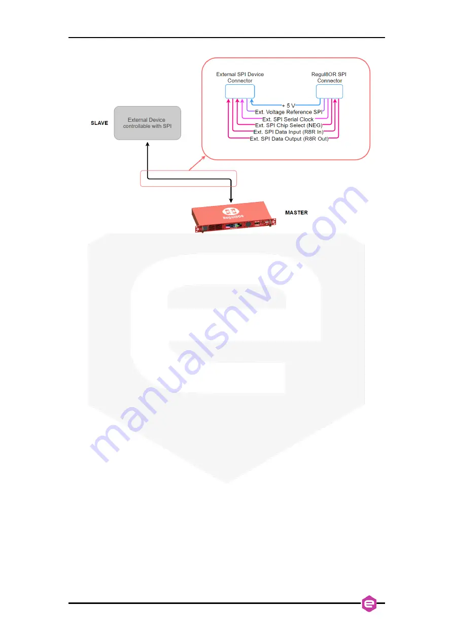
Figure 10:
schematic representation of a connection between the Regul8OR and a generic external
device made with the SPI
1.9
Output Connectors
The REGUL8OR has been designed to control an external power
stage/programmable power supply with an analog output voltage or, in specific cases,
an analog output current (to close a 4-20 mA loop).
Two connectors, an isolated BNC (voltage output) and a 4-pin LEMO (current
path and voltage output), are provided on the rear panel to feed the isolated output
signals.
Typically, a general-purpose programmable power supply can be controlled via
an external analog voltage with typical values ranging from 0 V to 10 V or from 0 V to
5 V (unipolar operation). In some specific applications, these signals can range from -
10 V to +10 V or from -5 V to +5 V (bipolar operation).
The analog output voltage is generated by a state-of-the-art 20-bit 1-MSPS
Digital to Analog Converter (DAC).
The 4-20 mA current control loop is often used in industrial process control. Its
name refers to the current range used to control or to measure in the loop, where the
current spans from a minimum value of 4 mA (0 %) to a maximum value of 20 mA
(100 % or full-scale). The main reason for the use of this current-based signal has to be
found in the fact that current signals are less sensitive to noise than voltage signals and
are so sometimes preferred in noisy environments – e.g. industrial facilities. The chosen
loop driver is a single-channel, 16-bit converter.


