RIVER IDROTECH 18 - 24 - 24H2O
28
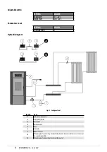
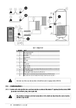
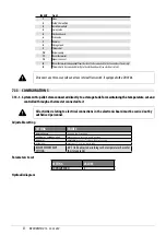
Fig. 44 - Configuration 5
LEGEND
1
Stove
2
Cold H2O manifold
3
Hot H2O manifold
4
3-way valve
5
Electronic board
6
Zone valve
7
Radiator
8
Storage tank
9
NTC probe
10
Release pump
11
Room thermostat
12
Expansion vessel
A
Room thermostat independent from the stove (to be connected to the zone valves, if necessary)
B
NTC probe to be connected directly to the electronic board (see electrical system)
Disconnect any three-way valve and stove internal flow switch, if equipped with a DHW kit.
7.14 CONFIGURATION WITH STORAGE TANK AND AUXILIARY WALL-MOUNTED BOILER (EXAMPLE)
7.14.1 System with: pellet stove connected to a storage tank with auxiliary wall-mounted boiler
All activities relating to electrical connections in the electronic board must be carried out by
authorised personnel.
Parameters to set
SETTING
VALUES
CONFIGURATION
1 - 2 - 3 - 4 - 5
AUXILIARY BOILER
ON


