SITE PLANNING AND INSTALLATION
Page 2 - 7
2.7
HUB ETHERNET CONNECTIONS
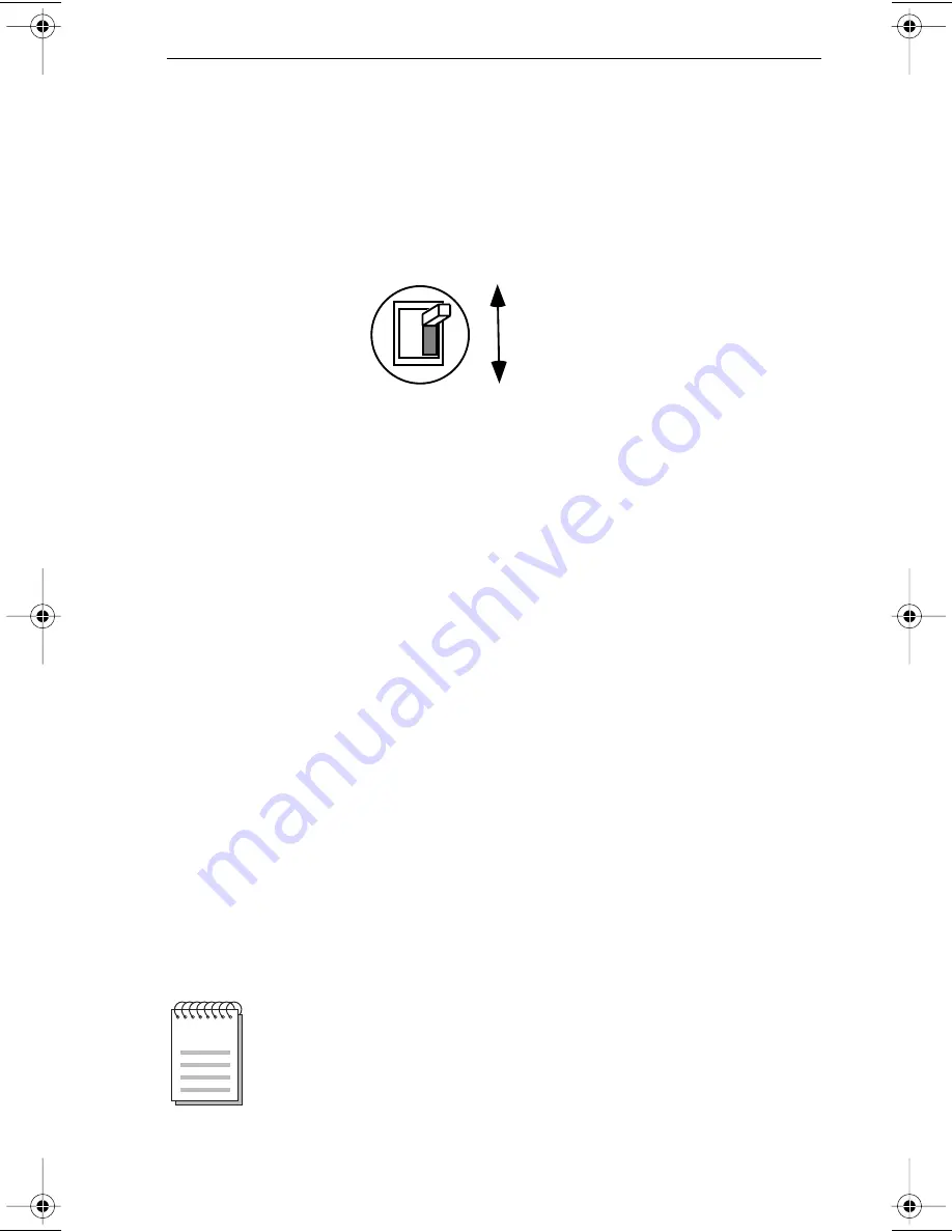
The wireless hubÕs Ethernet interface module incorporates a slide
switch that lets you select either port. To select the 10BASE-T port,
slide the switch all the way to the bottom. To select the AUI port,
slide the switch all the way to the top. See Figure 2-8, below.
Figure 2-8. Port Select Slide Switch
To connect the wireless hub to an existing 10BASE-T Ethernet
adapter, use standard, straight-through RJ-45 twisted pair cables.
You can connect the wireless hub to an external Ethernet
transceiver with a standard AUI cable.
2.8
HUB SETUP
Connect the antenna cable to the 25-pin D connector on the
wireless hub rear panel (see Figure 2-7) with the attached captive
screws. Position the wireless hub so that it is accessible to the
wired Ethernet backbone LAN or network segment.
The wireless hub antenna should be positioned above the wireless
hub chassis, on a Þle cabinet, a desktop, or a wall (see Figure 2-9 on
page -9). You can even hang the antenna from the ceiling if you
desire.
10BASE-T
AUI
NOTE:
Make sure that you do not obstruct the cooling air vents in the
top and bottom of the antennas.
FreeLink.Ch2.fixed Page 7 Wednesday, April 19, 2000 3:59 PM
Summary of Contents for FLIU-1
Page 2: ......
Page 4: ...ii NOTICE ...
Page 6: ...iv CONTENTS APPENDIX A TROUBLESHOOTING APPENDIX B TRANSCEIVER SERIAL NUMBERS ...
Page 16: ...Page 1 10 INTRODUCTION ...
Page 26: ...Page 2 10 SITE PLANNING AND INSTALLATION ...
Page 34: ...Page A 2 TROUBLESHOOTING ...
Page 36: ...Page B 2 TRANSCEIVER SERIAL NUMBERS Tcvr No Serial No Owner Location ...
Page 39: ......
Page 40: ...P N 9030833 May 1993 35 Industrial Way P O Box 5005 Rochester New Hampshire 03867 0505 ...


