22
22
5
Adjustments
5.2
Adjusting the Printing Mechanism
Major adjustment of the printing mechanism beyond format-based settings is only required if the printhead assembly
has been removed or parts in this area have been replaced. Excluded from this is the replacement of the printhead,
after which readjustment is generally not required.
The following print quality imperfections may indicate maladjustment of the printing mechanism:
• Print image too light
• Print image is spotty
• Print image lighter on one side
• Horizontal lines not parallel to the horizontal label edges
• Clear lateral drift of the transfer ribbon
i
Notice!
Print image errors can also arise from wrinkling of the transfer ribbon. This is why you should check the
transfer ribbon feed path and the head locking system for correct adjustment before making adjustments to
the printing mechanism
Operator's Manual.
The adjustment of both print unit can be carried out in the same manner and comprises the following procedures in
the order specified:
1. Prepare the label printer for adjustment
2. Adjust the position of the printhead
3. Adjust the printhead pressure
4. Adjust the transfer ribbon feed path
5. Perform a final test
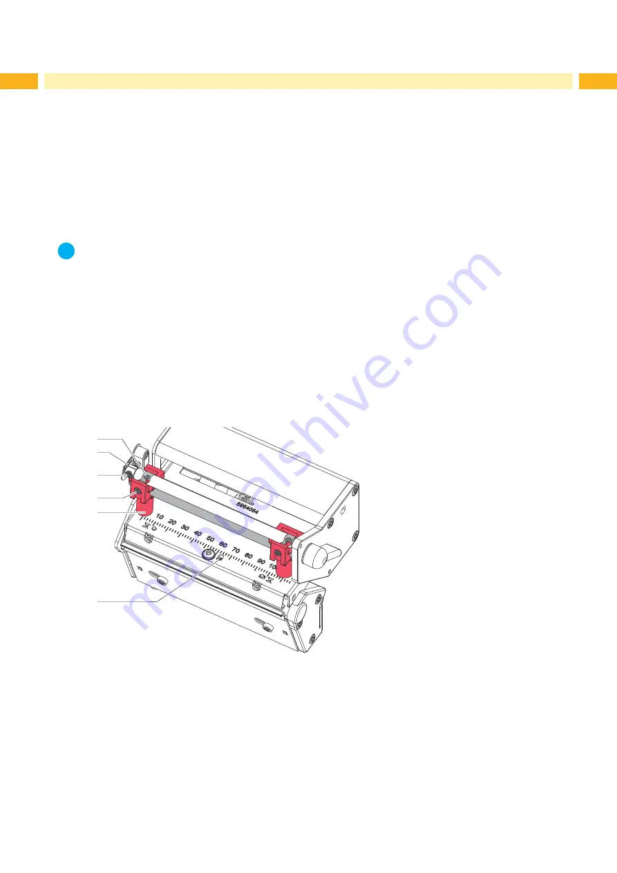
5.2.1 Preparing the Printer for Adjustment
2
3
4
5
1
6
Fig. 20
Preparing the printer for adjustment
1. Load labels and transfer ribbon which extend across the entire printing width.
2. In the printer configuration, set the
Heat level
parameter to -5 and the
Print speed
parameter to 100 mm/s.
3. Move the transfer ribbon deflection to the central position (2) with the screw (3).
4. Loosen screws (4) and position the plungers (5) in such a way that the adjustment screws are accessible through
the holes (1) of the square axis.
5. Loosen the screw (6) for the printhead bowing with an Allen key (1.5 mm) and turn it counterclockwise until turning
becomes perceptibly easier. This should occur after a maximum of a half a rotation.
6. Continue with the adjustment of the printhead position
Summary of Contents for XC Series
Page 1: ...Service Manual Label Printer XC Series ...
Page 34: ...34 34 7 Block Diagram Fig 32 Block diagram ...
Page 35: ...35 8 Layout Diagram CPU Fig 33 Layout diagram CPU components side ...
Page 36: ...36 36 8 Layout Diagram CPU Fig 34 Layout diagram CPU soldering side with measuring points ...


