background image

7

1 Introduction

1.7 

Labels and Transfer Ribbon

!

Attention!

Only wrap-around labels provided by the manufacturer guarantee proper applications.

Item surfaces must be clean and free of lubricants.
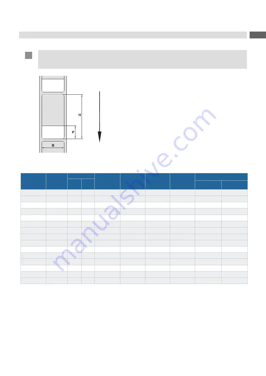
Feed direction

Figure 2  Label dimensions

Part no.

Data block

color

Item Ø

Label width 

mm

Printing area


height

 P


mm

Label height 

mm

No. of labels 

on a roll

R71 resin ribbon

D1 

mm 

D2 

mm

Width

mm at least

Part no.

5780120.130

white

2.0

4.0

12.7

   6.4

19.1

 7,450

25

5557401.133

5780121.130

white

2.0

4.0

25.4

   6.4

19.1

7,450

40

5557410.133

5780122.130

white

3.0

5.0

25.4

9.5

25.4

5,800

40

5557410.133

5780128.130

white

4.0

8.0

12.7

12.7

38.1

4,000

25

5557401.133

5780129.130

white

4.0

8.0

19.1

12.7

38.1

4,000

40

5557410.133

5780130.130

white

4.0

8.0

25.4

12.7

38.1

4,000

40

5557410.133

5780131.130

white

4.0

8.0

50.8

12.7

38.1

4,000

55

5557402.133

5780133.130

white

6.0

14.0

25.4

19.1

63.5

2,450

40

5557410.133

5780135.130

white

6.0

14.0

38.1

19.1

63.5

2,450

55

5557402.133

5780136.130

white

6.0

16.0

25.4

19.1

70.0

2,250

40

5557410.133

5780137.130

white

6.0

16.0

50.8

19.1

70.0

2,250

55

5557402.133

D1 - 

Up to this value, the printing area covers the circumference of an item.

D2 - 

Up to this value, the protective laminate covers the printing area

With labels 19.1 mm to 63.5 m mm high (H), items of diameters 2 mm to 16 mm can be labeled. Using labels 70 mm 
high, the smallest possible item diameter is 6 mm.

Table 2 

Labels and transfer ribbon

Summary of Contents for WICON

Page 1: ...Instructions WICON MADE IN GERMANY Wrap around applicator ...

Page 2: ...rformances are effected under the General conditions of sale of cab Further documentation Operator s Manual SQUIX https www cab de media pushfile cfm file 2771 Configuration Manual cab Printers https www cab de media pushfile cfm file 3257 Programming Manual cab Printers https www cab de media pushfile cfm file 3047 Instructions Germany cab Produkttechnik GmbH Co KG Karlsruhe Phone 49 721 6626 0 w...

Page 3: ...g the Front Cover 8 2 1 2 Replacing Peel off Plate and Print Roller 8 2 2 Mounting the Applicator 9 3 Loading Materials 10 4 Settings 11 4 1 Setting the Lateral Position 11 4 2 Setting the Stop 11 4 3 Setting the Parallelism of Labels and Products 12 5 Operation 13 6 Configuration 14 6 1 Settings of the Printer Menu 14 6 2 Special JScript Commands 15 7 Fault Correction 16 8 Approvals 17 8 1 Refere...

Page 4: ...sories peripheral equipment special fittings Time Information in the display 1 2 Intended Use The device has been designed for operations with SQUIX series printers being an option for labeling cylindric items of diameters 2 mm to 16 mm such as single wires strands cables hoses tubes or round rods Any other use has not been intended The manufacturer supplier is not liable for damages resulting fro...

Page 5: ...ped with tools that are necessary to do this job properly Do not remove warning stickers Dangers cannot be identified any longer Warning This is a class A product In a domestic environment this product may cause radio interference in which case the user may be required to take adequate measures 1 4 Safety Marking Figure 1 Safety marking Risk of crushing by moving parts X Do not interfere in the ap...

Page 6: ...max 1 Label Width mm 12 7 50 8 Height mm 19 1 70 0 Material PVC ApplicatorRates as for printing and applying a label s 1 8 6 No of wrap arounds 2 10 Start as soon as an item has been inserted by hand via data interface via I O interface Label printer SQUIX 4 MP Material guidance on the printer centered Print method Thermal transfer Print resolution dpi 300 600 Print speed mm s max 200 150 Print wi...

Page 7: ...8 0 12 7 12 7 38 1 4 000 25 5557401 133 5780129 130 white 4 0 8 0 19 1 12 7 38 1 4 000 40 5557410 133 5780130 130 white 4 0 8 0 25 4 12 7 38 1 4 000 40 5557410 133 5780131 130 white 4 0 8 0 50 8 12 7 38 1 4 000 55 5557402 133 5780133 130 white 6 0 14 0 25 4 19 1 63 5 2 450 40 5557410 133 5780135 130 white 6 0 14 0 38 1 19 1 63 5 2 450 55 5557402 133 5780136 130 white 6 0 16 0 25 4 19 1 70 0 2 250 ...

Page 8: ...bearing plate 6 using a 2 5 mm Allen key X Pull the standard print roller 8 off the shaft 3 and through the bearing plate 6 X Clean the shaft 3 X Set a narrow rubbered print roller 5 onto the shaft 3 and turn the roller slightly until the hexagon of the shaft connects with the internal hexagon of the print roller X Set the roller bearing 7 onto the roller pin and screw in the bearing plate 6 X Att...

Page 9: ... 1 on the printer X Push the applicator to the printer to connect the applicator plug with the peripheral port 2 of printer X Tighten the screw 4 to fix the applicator i Note The wrapper unit can be pivoted from the printer to insert materials and for service work 2 1 Figure 6 Pivoting the wrapper unit X Loosen the knurled screw 1 X Pivot the wrapper unit 2 from printer X When finished pivot back ...

Page 10: ... 2 Figure 7 Loading materials X Pivot the wrapper unit from the printer X Insert ribbon 1 and labels 2 as shown in the figure X Switch on the printer X Press to synchronize the paper feed X Remove blank labels provided on label feed X Pivot back the wrapper unit and fix it to the printer ...

Page 11: ...er margin 4 X Tighten the screw 2 4 2 Setting the Stop Using the stop results in accurate repeatability of label positioning i Note Markings on scale 3 are valid only with applicators set in the correct lateral position 4 1 on page 11 2 1 3 4 5 Figure 9 Setting the stop X Loosen the screw 1 X Set the scale 3 with the stop 4 so that the desired distance from the label margin to the end of the produ...

Page 12: ... around an item modify the angle of the applicator to the printer 2 1 3 Figure 10 Setting the parallelism X Loosen the knurled screw 2 X Pivot the wrapper unit 3 in small steps by turning the set screw 1 X Tighten the knurled screw 2 X Start labeling and check the result X Modify the setting if required 4 Settings ...

Page 13: ... necessary adjust the position via Setup Labelling Peel off position 5 2 Creating a Layout 5 2 1 Activating the Peel off Mode X Activate the peel off mode in the software This is done with the P command in the direct programming Programming Manual 5 2 2 Job Related Correction of the Peel off Position X Observe the peel off position during operation X Do not change the basic setting 5 1 2 but corre...

Page 14: ...ntering panels by inserting the product and keep tight flexible material As soon as both panels are closed the applicator is ready for labeling 6 5 2 6 5 2 þ ý Figure 13 Product in centering panel Attention X When the product 2 is inserted with excessive power it can be moved beyond the axle 6 of the appli cator Following the labels can form loops on the product X Depending on the setting wrapping...

Page 15: ...y inserted the diameter of the calibrating product can be set Reset service counter Access only with service key inserted Reset of the applicator s service counter Cycle sequence Select type of operation Print apply Printing a label and applying it to an item are triggered by a START signal After a cycle has finished the transport module contains no label Apply print Printing an initial label is t...

Page 16: ... automatically be stored and considered for future measurements 6 2 Special JScript Commands i Note Some parameters of the menu Setup Labelling can be changed or overridden by JScript commands in a print job These changes are valid for the current print job only Attention The meaning of the commands O Ax y in the following table are valid for WICON only For other applicators the meaning of these c...

Page 17: ... labels and product from the applicator X If error recurs call service No product detected The diameter recognized by the applicator is under the defined minimum diameter X Use products with correct diameters Wrapping failed Failure of the wrapping unit movement X Remove labels and product from the applicator X If error recurs call service Table 5 Fault correction How to remove labels from the app...

Page 18: ... media pushfile cfm file 3982 8 2 FCC NOTE This equipment has been tested and found to comply with the limits for a Class A digital device pursuant to Part 15 of the FCC Rules These limits are designed to provide reasonable protection against harmful interference when the equipment is operated in a commercial environment The equipment generates uses and can radiate radio frequency and if not insta...

Reviews: