background image

cab - Produkttechnik GmbH

24

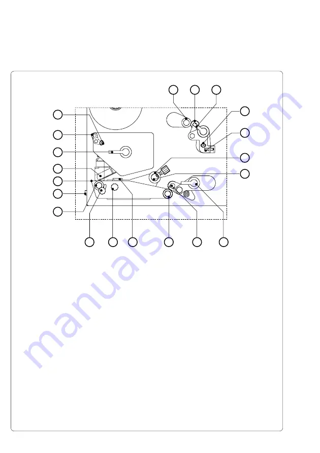
Fig. 4e  Detailed view of the print mechanism Hermes 4N/5N

1

- Backfeed roller

2

- Backfeed system locking unit

3

- Backfeed system locking lever

4

- Locking screw for label track adjustment

5

- Set screw for label track adjustment

6

- Media guide with locking screw

7

- Media guide axle

8

- Transport system locking lever

9

- Transport system locking unit

10

- Transport roller

11

- Label edge sensor

12

- Knurled knob to adjust the label edge sensor

13

- Printhead levelling adjustment screw

14

- Print roller

15

- Socket of the peripheral port for cab-applicators

16

- Peel-off edge

17

- Thermal printhead

18

- Printhead locking lever

19

- Adjustable axle for ribbon track adjustment

20

- Locking screw for ribbon track adjustment

2

1

8

9

14

16

15

3

4

5

6

7

10

11

12

13

17

18

19

20

Summary of Contents for Hermes 4F

Page 1: ...Edition 8 00 Transfer Printer Hermes Hermes 4N Hermes 5N Hermes 4F Hermes 5F Technical Information ...

Page 2: ...inual product improvement we reserve the right to alter specifications without notice Données technique modifiables sans prévais cab Produkttechnik Gesellschaft für Computer und Automations Bausteine mbH Co KG Postfach 19 04 D 76007 Karlsruhe Wilhelm Schickard Str 14 D 76131 Karlsruhe Telefon 0721 66 26 00 Telefax 0721 66 26 249 ...

Page 3: ...es All rights reserved including those of the translations No part of this manual nor any translation may be reproduced or transmitted in any form or by any means for any purpose other than the purchaser s personal use without the express written permission of cab Produkttechnik GmbH Karlsruhe Edition 8 00 Printed in Germany ...

Page 4: ...ware EASYLABEL for Windows 14 Print Media 15 Print Media for Direct Thermal Printing 16 Print Media for Thermal Transfer Printing 16 Label Tag Media Specifications 17 Transfer Ribbon 18 2 General Safety Instructions 19 3 Delivery Contents 19 4 Printer Component Location 20 5 Connecting the Printer 28 Connection to Power Supply 28 Connection to a Computer 29 Switch on the Printer 30 6 Media Loading...

Page 5: ...rror Messages 56 Correctable Errors 56 Irrecoverable Errors 56 Appendices Appendix A Built in Dimensions A 1 Hermes 4N A 2 Hermes 4F A 3 Hermes 5N A 4 Hermes 5F A 5 Appendix B Pin Assignment of the Interface Connectors B 1 Pin Assignment of the Serial Interface Connector B 1 Interface Cable for RS 232 B 2 Interface Cable for RS 422 RS 485 B 3 Pin Assignment of the Parallel Interface Connector B 4 ...

Page 6: ... in the creation of this manual to provide as much information as possible in an understandable manner We welcome your comments and suggestions regarding additions or corrections to improve future editions of this manual Please let us know if you have any questions Further Documentation Complete information on the use of the Hermes printers are included in the Operator s Manual The programming of ...

Page 7: ...rs Under disadvantageous circumstances the operation of these devices may cause interference with radio or TV reception which has to be eliminated by the operator Trademarks Centronics is a registered trademark of Centronics Data Computer Corporation Macintosh Computer is a product of Apple Computer Inc Microsoft is a registered trademark of Microsoft Corporation Bitstream is a registered trademar...

Page 8: ...jects on the labels in order to avoid impurification of the printhead This way the printhead might be damaged 3 Use proper label material with a smooth surface only A rough surface will affect the printhead and may cause damage and reduce its operating life 4 Clean the printhead regularly with a special printhead cleaning pen or an isopropyl alcohol soaked cotton swab 5 Print with the lowest possi...

Page 9: ...Apollo printers With the high class printheads 305 dpi near edge printhead at Hermes 4N 5N or 300 dpi flat printhead at Hermes 4F 5F it is possible to print bar codes and graphics quick brilliant and tidy The double lined LCD display keeps the operator constantly informed about the current status of the printer The setup menu allows easy configuration changes whenever desired The options PCMCIA me...

Page 10: ...bel supply roll Hermes 4N 4F 7 9 200 mm Hermes 5N 5F 11 8 300 mm Further the devices only will be called as Hermes where are no differences between the types Overwiew of the Optional Features For the devices of the Hermes familiy the following optional features are available Part No Description 5537742 Warning Sensor Label End Hermes 4 5537743 Warning Sensor Ribbon End Hermes 4 5537744 Warning Sen...

Page 11: ...n and Eastern European Latin characters Character size For scaleable fonts width and height 035 to 5 in 0 9 128mm are individually changeable For Bitmap fonts width and height 04 to 12 in 1 3 mm the size is selectable up to a factor of 10 Font style bold italic underlined mirror inverted outlined revers grey Font rotation Bitmap fonts Bar codes 0 90 180 270 Scaleable fonts optional texts in circul...

Page 12: ...fter the completion of the previous label print To avoid an abrasion of the transfer ribbon at the label the printhead wil be lifted during the backward transport Test features System test when switching on Self test with printout of firmware data and system parameters Label material Thermal paper normal paper plastic foil PE PP PVC Polyamide Adhesive labels 60 160 g sqm Material width 4 7 in 120 ...

Page 13: ...Information via peripheral interface and warning light at passing the adjusted minimum diameter of the supply roll of labels or transfer ribbon if the warning sensors are installed Dimensions Hermes 4N 4F Heigth 15 4 in 390 mm Width 10 9 in 277 mm Depth 16 5 in 420 mm Hermes 5N 5F Heigth 21 3 in 542 mm Width 10 9 in 277 mm Depth 21 3 in 542 mm Weight Hermes 4N 4F 46 3 lb 21 kg Hermes 5N 5F 55 2 lb...

Page 14: ...m quantity of labels or transfer ribbon is passed PC Memory Card Hermes includes an option for using memory cards in order to permanently store graphics fonts databases or whole label formats The data can be downloaded via interface PCMCIA 2 1 conforming sRAM cards or Flash EPROM cards are accepted The maximum capacity is 4 MegaByte Using a memory card the printer can be operated without being con...

Page 15: ...peed Thus the Hermes offers a wide range of opportunities for usage Hermes 4N and Hermes 4F are able to print on labels with a maximum supply roll diameter of 8 in 200 mm and a core diameter of 3 in 76 mm Hermes 5N and Hermes 5F can use labels with a maximum supply roll diameter of 12 in 300 mm and a core diameter of 3 in 76 mm The ability of label edge recognition which guarantees the precise pos...

Page 16: ...ermal coating quickly resulting in damage to the printhead 2 The surface of the labels should be very smooth to avoid a sandpaper effect on the printhead 3 Always choose material which can be printed on with the lowest possible heat level The greater the heat level the shorter the life of the printhead Moreover with highest heat levels the phases of heating up and cooling down extend This may have...

Page 17: ...H Item MIN MAX A Label width 4 10 4 6 116 B Width of the silicon liner 4 10 4 7 120 C Label length 2 5 21 5 546 D Gap between labels 08 2 21 5 546 E Label thickness 0024 06 01 25 F Thickness of silicon liner 002 05 004 1 G Distance of the first printing point from the edge of silicon liner 0 H Distance of the label sensor from the edge of silicon liner 08 2 1 85 47 I Width of punch hole 2 5 K Heig...

Page 18: ...electronic protection Poor transfer ribbons also tend to lose parts of the coating which leads to accumulating dirt on the printhead and the sensors With some ribbons the color rubs off and soils the printhead All of these effects contribute to poor print quality We have carried out numerous tests with many different ribbons and we recommend you use transfer ribbons made by well known brand manufa...

Page 19: ...her 230V or 115V power supply which can be switched using the input voltage selector at the back of the printer Connect only to a power outlet with a grounded contact The printer must only be connected to devices which have extra low voltage Power must be OFF before plugging in any accessory or connecting the printer to a computer etc Also switch power off on all appliances before disconnecting Do...

Page 20: ...ction keys with indicator LEDs 3 Power switch 4 Swing arm with guide roller 5 Media supply hub 6 Adapter 7 Flange 8 Knurled knob 9 Media rewind hub 10 Guide roller 11 Print mechanism Fig 4e 12 Knurled knob 13 Ribbon take up hub 14 Knurled knob 15 Ribbon supply hub 1 2 3 4 6 8 9 10 11 12 15 13 14 5 7 ...

Page 21: ...nsfer ribbon end 4 Connector warning sensor label end 5 Swing arm with guide roller 6 Media supply hub 7 Adapter 8 Flange 9 Knurled knob 10 Media rewind hub 11 Guide roller 12 Print mechanism Fig 4e 13 Knurled knob 14 Ribbon take up hub 15 Knurled knob 16 Ribbon supply hub 17 Power switch 1 2 3 4 5 6 9 10 11 12 13 14 15 16 7 8 17 ...

Page 22: ... indicator LEDs 3 Power switch 4 Swing arm with guide roller 5 Media supply hub 6 Adapter 7 Flange 8 Knurled knob 9 Media rewind hub 10 Guide roller 11 Print mechanism Fig 4f 12 Knurled knob 13 Ribbon take up hub 14 Knurled knob 15 Ribbon supply hub 1 2 3 4 6 8 9 10 11 12 15 13 14 5 7 ...

Page 23: ...nsfer ribbon end 4 Connector warning sensor label end 5 Swing arm with guide roller 6 Media supply hub 7 Adapter 8 Flange 9 Knurled knob 10 Media rewind hub 11 Guide roller 12 Print mechanism Fig 4f 13 Knurled knob 14 Ribbon take up hub 15 Knurled knob 16 Ribbon supply hub 17 Power switch 1 2 3 4 5 6 9 10 11 12 13 14 15 16 7 8 17 ...

Page 24: ...dia guide axle 8 Transport system locking lever 9 Transport system locking unit 10 Transport roller 11 Label edge sensor 12 Knurled knob to adjust the label edge sensor 13 Printhead levelling adjustment screw 14 Print roller 15 Socket of the peripheral port for cab applicators 16 Peel off edge 17 Thermal printhead 18 Printhead locking lever 19 Adjustable axle for ribbon track adjustment 20 Locking...

Page 25: ...stem locking unit 8 Transport roller 9 Media guide with locking screw 10 Media guide axle 11 Label edge sensor 12 Knurled knob to adjust the label edge sensor 13 Printhead levelling adjustment screw 14 Print roller 15 Socket of the peripheral port for cab applicators 16 Peel off edge 17 Ribbon shield 18 Thermal printhead 19 Printhead locking lever 20 Adjustable axle for ribbon track adjustment 21 ...

Page 26: ... ribbon end Hermes 4N 4F only 5 Connector warning sensor label end Hermes 4N 4F only 6 Connector warning light 7 Drillings for mounting a compressed air service unit option 8 Memory card module slot 9 Drillings for mounting a bracket option 10 Parallel interface port 11 Serial interface port 12 Plug of the peripheral port for non cab applicators 1 2 3 5 4 9 8 6 11 10 7 12 ...

Page 27: ...27 cab Produkttechnik GmbH ...

Page 28: ... selector 1 from the power unit CAUTION If you have changed the operating voltage of your printer the fuses 6 need replacing as stated below 230V 2 x T 4A 115V 2 x T 6 3A When delivered the correct fuses for the pre selected operative voltage are installed You will find the necessary fuses for the other voltage in the accessories package Slide the voltage selector back into the power supply module...

Page 29: ... the serial port the Hermes also provides a parallel Centronics interface which offers a faster transfer of data than the serial interfaces Therefore we recommend you use the parallel interface for those applications where a large number of loadable fonts or complex graphics have to be printed For the Centronics interface use the 36 pin interface connector 1 Select the required interface settings ...

Page 30: ...ase check the following whether the connection of the power switch is correct the setting of the voltage selector corresponds with the power supply voltage the fuses in the voltage selector are not defective If all these conditions are true and the device nevertheless cannot be switched on call for service please CAUTION If the fuses in the voltage selector are defective do not use the fuses of th...

Page 31: ...unt two adapters 3 onto the supply hub 1 Put the first adapter 3 onto the supply hub 4 and slide it to the wind plate 1 until it blocks Tighten the knurled srew 2 2 Put the second adapter onto the supply hub 4 and slide it against the wind plate until the distance between the outer edge of the adapter and the wind plate 1 is a little less than the width of the label roll Tighten the knurled screw ...

Page 32: ...ly hub 3 slide it against the label roll 1 and fix it at the supply hub by tightening the knurled knob 2 3 Swing the three levers 9 19 und 16 clockwise until they stop and open this way the transport system 10 11 and the backfeed system 17 18 The printhead 15 also will be unlocked from the print roller 4 Loosen the knurled knob 12 and slide the media guide 13 into its outermost position Fig 6b Med...

Page 33: ...7 Slide the media strip under the rewinder clamps 6 to the wind plate Hold the rewinder and turn the knurled knob 7 clockwise That way the label strip will be fixed at the rewinder 8 Turn the rewinder 8 clockwise for tightening the label strip 9 Slide the guide 13 against the outer edge of the label strip and tighten the knurled knob 12 10 Swing all levers 9 19 and 16 counterclockwise until they b...

Page 34: ...de wound ribbon and the broken line represents the path of outside wound ribbon 3 Hold tight the ribbon supply hub 7 and rotate the knurled knob 8 clockwise until it stops That way the transfer ribbon roll 6 will be attached to the ribbon supply hub 7 4 Slide an empty cardboard core 1 onto the ribbon take up hub 2 and fix it by clockwise turning the knurled knob 3 5 From the side feed the transfer...

Page 35: ...gs or deviate from the square or rectangular shape It is important to ensure that the sensor is positioned in a way that the gaps between the labels or the markings can be recognized by the photocell The position of the sensor is marked by a notch in the sensor holder If using labels with an unconventional shape i e round or curved the sensor should be positioned at the front edge of the label Adj...

Page 36: ...as follows 1 Loosen the knurled screw 3 2 Move the knurled screw 3 as required within the adjustment slot 4 This will cause the cam shaped printhead support 2 to rotate in effect providing a higher or lower base on which the printhead mounting 1 rests 3 It is convenient to use the position 3a to print large labels In this case the printhead support 2 is totally inactiv 4 By using small labels it i...

Page 37: ...of the peel position a paper jam or a damage of the label strip To correct this problem the backfeed system may be adjusted as follows 1 Loosen the locking screw 2 at the backfeed system 2 Adjust the label tracking by turning the set screw 3 If the labels drift inwards ð Turn the set screw clockwise If the labels drift outwards ð Turn the set screw counterclockwise Repeat the adjustment as long as...

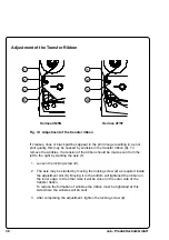
Page 38: ...the left to the right by slanting the axle 1 1 Loosen the locking screw 2 2 The axle may be slanted by moving the locking screw 2 as required inside the adjustment slot 3 Moving it to the bottom will tightened the ribbon on the inner edge In the other case it will be done on the outer side of the transfer ribbon To reduce the formation of wrinkles the ribbon must be tightened at this side where th...

Page 39: ...1 Print start Since the label will be dispensed from the liner directly after printing it is necessary to make sure that the applicator is ready to take the label when sending the signal Print start 2 Label is taken This signal is needed to start the backfeed of the label material After the backfeed the print of the next label can be started from the front edge It is also necessary to activate thi...

Page 40: ...b types of Hermes have aditionally a second peripheral port 3 at the front side Typically for the cab applicators the dispensed label will be taken by a vacuum plate 2 After that different pneumatic cylinders move the plate to the labelling position where the label will be pressed or blown onto the product The size of the vacuum plate is specified for the label size cab Applicators ...

Page 41: ...licator downwards blow on with Lift Cylinder Tamp Applicator sidewards press on with Swing Lift Cylinder Blow Applicator sidewards blow on with Swing Cylinder upwards Table 8 cab applicator types For use in a networked system all cab applicators are equipped with a PLC interface with potential free inputs and outputs For the detailled description of the cab applicators several Operator s Manuals a...

Page 42: ...The delivery contents of the bracket 1 include a clamp 2 for mounting the bracket 1 at a profile with a cross section of 50mmx50mm The clamp is made of three parts assembled by screws 3 1 2 3 Fig 8 c Bracket with clamp The form of the clamp allows to mount the bracket onto a horizontal as well as a vertical profile Besides the bracket can be moved sideward inside the clamp This way the bracket can...

Page 43: ...ounting the printer at the bracket Hermes has one each bolt 4 at the front and the rear side Using these bolts the printer is hung in into the grooves of the bracket 1 After that the printer is fixed at the bracket with six screws 5 4 1 5 ...

Page 44: ...lso possible to mount the printer onto a customer specific head plate The feet are fixed from below with four screws at the frame of the printer The shorter foot has to be mounted below the print machanism Fig 8 f Feet Fig 8 g Set up the printer on a table Fig 8 h Set up the printer on a head plate ...

Page 45: ...3 Use the two screws 2 which are included in the delivery contents of the light 2 Contact the connection cable 4 of the warning light at the socket 5 During the operation the lamps have following functions green Device is switched on voltage is available yellow Warning labels respectively transfer ribbon have passed the preset minimum quantity Function is only available when the warning sensor lab...

Page 46: ...ing plate The hexagon socket head screw 3 must be used at this side where the elongated hole is located in the sensor holder 4 Plug the cable 4 For that Hermes 4 has a 5 pin connector at the rear side of the frame The connector 10 at Hermes 5 is beside the control panel Adjustment With this setting the threshold diameter 3 3 to 4 3 in 84 to 110mm for the warning message can be adjusted 1 Slide a l...

Page 47: ...47 cab Produkttechnik GmbH Fig 8 k Warning sensor label end Hermes 4 Fig 8 l Warning sensor label end Hermes 5 10 4 2 7 1 6 5 8 3 9 1 2 3 4 5 7 8 9 4 6 ...

Page 48: ... hubs as shown in fig 8m Make sure that the distance between the reflective foil and the mounting plate 1 is about 0 6in 15mm Fig 8 m Placing the reflective foil 15 15 20 1 2 3 Adjustment With this setting the threshold diameter 1 4 to 1 6in 34 to 41mm for the warning message can be adjusted 1 Slide a transfer ribbon roll 4 with the intended threshold diameter onto the media supply hub 2 Switch on...

Page 49: ...49 cab Produkttechnik GmbH Fig 8 n Warning sensor ribbon end Hermes 4 Bild 8 o Warning sensor ribbon end Hermes 5 2 3 5 4 7 6 9 8 3 10 9 8 6 7 4 5 2 3 ...

Page 50: ...50 cab Produkttechnik GmbH ...

Page 51: ...e operator with the actual information concerning the current printer mode and label processing The indicator LEDs support the information shown in the display by indicating which keys have to be pressed e g in the event of a fault On the following pages you will find descriptions of the system modes of the Hermes the related indications by the LCD display an the LEDs as well as a description of t...

Page 52: ...econds will switch into the SETUP mode CAN key LED ONL off System Mode ONLINE ONL key Switch into ONLINE mode LED ONL on FF key Provides label feed The leading edge of the next label to be printed is in print position CAN key Switch into LABEL FROM CARD mode only if memory card is installed and formats are stored it PSE key Display shows current printer mode System Mode OFFLINE System Mode PRINT C...

Page 53: ...nt job Switch into PRINT mode LED PSE off ONL key Switch into OFFLINE mode FF key For scrolling down within the file list stored on the card Reduces the quantity of labels to be print CAN key For scrolling up within the file list of the card Increases the quantity of labels to be printed PSE key Confirms file selection Moves the cursor to be right when setting the quantity of labels to print Switc...

Page 54: ...point by pressing the key The confirmed parameters will be saved To return to the original factory default settings press all three keys the key the key and the key simultaneously and keep them pressed down until the display shows RESTORE ONL key Stores the chosen settings of the setup parameters and completes the SETUP mode i e switch into ONLINE mode LED ONL on FF key Skips to next setup paramet...

Page 55: ...rsion xxxxx xxx m xxx h Set date DD 00 0000 00 MM 0000 00 00 YYYY Set time hh 00 00 00 mm 00 00 00 ss Character set ISO 8895 1 Codepage 850 EBCDIC Macintosh Codepage 852 ISO 8895 8 Windows 1252 Windows 1250 Format card No Yes Copy memory card Yes No Label sensor Gap sensor Bottom Reflect Top reflect Country Deutschland France United Kingdom USA Schweiz Suisse Belgie Suomi Italia España Ceska repub...

Page 56: ...itch into ONLINE mode LED ONL on LED CAN off LED PSE off PSE key Continues current print job after error correction Switch into PRINT mode LED ONL on LED CAN off LED PSE off Irrecoverable Errors While switching on the printer or during printing a fault has occured which cannot be cleared by the operator without cancelling the current print run e g hardware fault Display This display shows the type...

Page 57: ...r and standard mounting elements e g flange FKV 50 respectively profile EV 50 of the firm Rose Krieger Verbindungstechnik GmbH will be delivered The feet of Hermes are shaped in such a way that the printer may be fitted at the setting area with suitable clamps and so the Hermes will be saved against sliding CAUTION If you have purchased the printer without feet avoid to place it upright Due to the...

Page 58: ...Feet 2 Compressed air service 3 Tamp Applicator with Lif 5537950 4 1 3 4 212 164 55 4 220 27 15 max 120 97 5 334 43 50 252 5 77 18 89 55 5 22 223 36 277 113 490 390 10 43 7 8 16 2 5 17 420 245 7 128 42 7 157 sfer Printer Hermes 4N 7500 471 ket 748 pressed air service unit Applicator with Lift Cylinder Type 1100 220 H 950 245 7 128 ...

Page 59: ...rvice unit 3 Tamp Applicator with Lift Cylind 5537950 4 1 3 4 o 15 max 120 77 18 502 7 72 334 43 o 50 55 4 27 10 55 223 220 36 158 98 2 5 17 152 245 7 42 7 128 212 16 390 277 22 89 113 55 5 420 157 5942471 ansfer Printer Hermes 4F 37503 acket 37748 et mpressed air service unit mp Applicator with Lift Cylinder Type 1100 220 H 37950 245 7 128 42471 ...

Page 60: ...et 3 2 1 Tamp Applicator with Lift Cylinder Type 1 4 4 3 1 5537950 1 164 55 4 220 max 120 457 50 334 43 15 253 193 77 18 230 36 277 113 89 55 5 22 490 457 542 7 8 7 8 43 27 10 2 5 16 17 542 219 128 245 7 42 7 7748 mpressed air service unit ket 2472 sfer Printer Hermes 5N 7501 p Applicator with Lift Cylinder Type 1100 220H 7950 43 128 245 7 ...

Page 61: ...ermes 5F 5537506 Feet 3 2 1 Tamp Applicator with Lift Cylinder Type 1 4 4 3 1 5537950 1 220 152 55 4 max 120 457 50 334 43 15 253 193 77 18 230 36 277 113 89 55 5 22 542 502 457 55 27 10 2 5 16 17 542 219 128 245 7 42 7 8 ssed air service unit 2 r Printer Hermes 5F 6 pplicator with Lift Cylinder Type 1100 220H 0 28 245 7 ...

Page 62: ...it Data RS 422 RS 485 18 RDATA Receive Data RS 422 RS 485 19 RDATA Receive Data RS 422 RS 485 20 DTR Data Terminal Ready Appendix B Pin Assignment of the Interface Connectors Pin Assignment of the Serial Interface Connectors Hermes provides a 25 pin SUB D connector for the serial interfaces which are internally available i e RS 232 RS 422 and RS 485 Table B 1 Signals of the serial interface connec...

Page 63: ...s some typical RS 232 interface cable configura tions Note that the pin assignment may vary for different computers If you have any problems with the connections contact the manufacturer of your computer on the pin assignment of the interface Use the pin assignment of the printer as shown in Table B 1 to obtain a suitable cable PC Hermes 9 pin connector 25 pin plug 2 2 3 3 5 7 8 20 1 4 4 5 6 PC He...

Page 64: ... TDATA TDATA RDATA and RDATA are necessary Check the pin assignment for the interface of your computer and use the pin assignment of the printer as shown in table B 1 to obtain a suitable cable The connectors of TDATA and RDATA as well as TDATA and RDATA at the plug in connection of the cable must be united If there is a very large transfer distance a termination of the cables is recommended PC He...

Page 65: ...GND 4 DATA 3 13 SLCT 22 GND 31 nc 5 DATA 4 14 nc 23 GND 32 nc 6 DATA 5 15 nc 24 GND 33 nc 7 DATA 6 16 GND 25 GND 34 nc 8 DATA 7 17 nc 26 GND 35 nc 9 DATA 8 18 nc 27 GND 36 nc Pin 18 Pin 1 Pin 19 Pin 36 Centronics Interface Cable The cables used for Centronics interface connectors are standard cables so that normally there are no problems with the external control of the Hermes In the event of any ...

Page 66: ...ters have an additional interface with a 15 pin SUB D socket at the front side Fig B 7 Plug of the Peripheral Connector Table B 3 Pin Assignment of the Peripheral Connector Plug Pin 1 Pin 8 Pin 15 Pin 9 Pin Direction Description 1 output printer not ready 2 output label is printed 3 output printer error 4 output print job available 5 output green device is switched on 6 input external error 7 inpu...

Page 67: ...Print start 8 15 Label was taken 7 14 External error 6 13 Table B 4 Pairs of input signals For each signal IN there is a separate reverse line IN R via the plug connector From that the following pairs of signals result All outputs are switched by relays which all have one common reverse line PIN 10 of the the plug OUT Reverse line Pin10 Fig B 9 Circuit of the outputs Electrical requirements Umax 4...

Page 68: ...ion of the Hermes The details and type of error can be learnt from the printer display Ribbon out Paper out No label If the signal is active the relay in the output circuit is closed After error correction the print of the last label will be repeated The error activates the signal Printer not ready too Print job is available Hermes has a print job requirement to print a new label If the signal is ...

Page 69: ...rt This releases the start of the print if there is no label in the peel position a print job was sent to the printer the printer is ready The signal is active in the live mode of the input circuit pin 8 pin 15 Warning transfer ribbon end Message of the warning sensor transfer ribbon end The diameter of the ribbon supply roll has decreased below the adjusted minimum value If the signal is active t...

Page 70: ...feed Locking System x x x x 5537667 Label Sensor Assy x x x x 5537698 Backfeed Roller x x x x 5537730 Wall Spacer x x 5537752 Printhead x x 5537753 Main Drive Motor x x x x 5537754 Ribbon Sensor Board x x x x 5537760 PCB CPU Hermes 4 5 x x 5537762 Stepper Motor x x x x 5537770 Transport Roller x x x x 5537771 Print Roller x x x x 5537775 Transport Locking Roller x x x x 5537845 PCB Driver Electron...

Page 71: ...er Hermes Applied EU Regulations and Norms EC Machinery Regulations 89 392 EEC Appendix IIA Machine Safety EN 292 T1 T2 1991 11 EC Low Voltage Regulations 73 23 EEC Data and Office Machine Safety EN60950 1992 A1 1993 EN 60950 A2 1993 EC Electromagnetic Compatibility Regulations 89 336 EEC Threshold values for the Interference EN 55022 1995 05 of Data Machines Interference Resistance in both EN 500...

Reviews: