background image

24

24

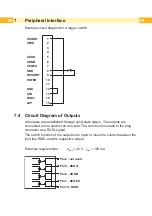
Example circuit diagram for a trigger switch :


XSTART

1

XFEH

2

3

4

XEDG

5

XDNB

6

XEGES

7

GND

8

RXSTART

9

RXFEH

10

11

GND

12

STA

13

RUEL

14

24P

15

7.4  Circuit Diagram of Outputs

All outputs are established through solid-state relays.  The outputs are 
connected to one another on one-side. The common line leads to the plug 
connector as a RUEL signal. 

The switch function of the outputs is to open or close the contact between the 
joint line RUEL and the respective output.

Electrical requirements : 

U

max

 = 42 V , I

max

 = 100 mA

Pin 4 - not used

Pin 5 - XEDG

Pin 6 - XDNB

Pin 7 - XEGES

Pin 14 - RUEL

Peripheral Interface

Summary of Contents for CU Series

Page 1: ...Made in Germany Cutter Operator s Manual CU Series...

Page 2: ...lease check www cab de for the latest update Terms and conditions Deliveries and performances are effected under the General conditions of sale of cab Germany cab Produkttechnik GmbH Co KG Postfach 19...

Page 3: ...12 5 Operation 12 5 1 Standard Operation 12 5 2 Operation Without Cover Plates 13 5 3 Operation with External Control 14 6 Maintenance 15 6 1 Cleaning 15 6 2 Changing the Blades 17 6 3 Setting the In...

Page 4: ...could lead to injuries or material damage Attention Draws attention to possible dangers material damage or loss of quality i Notice Gives you tips They make a working sequence easier or draw attentio...

Page 5: ...tenance recommendations and specifications The device is manufactured in accordance with the current technological status and the recognized safety rules However danger to the life and limb of the use...

Page 6: ...vice can also endanger operational safety Always have service work done in a qualified workshop where the personnel have the technical knowledge and tools required to do the necessary work Warning sti...

Page 7: ...rface for trigger switch or external control Attention The minimum cut length is depending on the media in particular its adhesive characteristics Perform preliminary tests Test the media too if the m...

Page 8: ...3 1 Loosen the screws 1 2 Place the cutter tray 2 on the screws 1 in front of the tear off plate or the dispense plate and slide it to the left until it stops 3 Tighten the screws 1 4 Adjust the lengt...

Page 9: ...ion with A printer there has to be mounted a tear off plate or a dispense plate on the printer to lead the material through the blades of the cutter 4 5 4 3 7 6 3 Insert the pins 3 of the cutter 7 int...

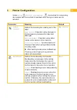
Page 10: ...cut position relative to the printed image Cut position with the initial offset value of 0 causes to cut in the middle of the gap between two labels If the cut position value is positive the media wi...

Page 11: ...ng mode X X After loading media press the feed key That way a short feed and a synchroni zation cut are realized Gap sensor Backfeed Method for backfeeding the material Backfeeding is necessary in the...

Page 12: ...n the printer menu Setup Print parameters Label sensor the setting Endless media has to be selected Otherwise no synchronization cut is carried out X X Switch on the printer The cutter performs a cut...

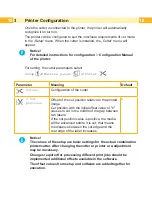
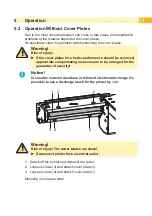
Page 13: ...rmance should be removed appropriate compensating measures are to be arranged for the guarantee of security i Notice In case the material do adhere in follow of electrostatic charge it s possible to u...

Page 14: ...the peripheral interface on the cutter i Notice This operating mode requires that there is a connection between Pin 13 STA and Pin 12 GND at the peripheral interface chapter Peripheral Interface The...

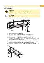
Page 15: ...ust and paper particles with a soft brush or a vacuum 4 For cleaning the circular blade it is possible to turn the axle 6 with a screwdriver for slotted head screws slot width 7 mm The rotation angle...

Page 16: ...l and the cutter blades 7 8 6 7 Grease the cylindrical area 7 of the circular blade 8 with an All round High quality Grease For that hold a greased brush on the cylindrical area and turn the axle 6 wi...

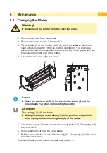
Page 17: ...rear of the cutter 4 Loosen the set screw 4 a few turns 3 2 1 4 i Notice X X Save the washers A B C for the circular blade 2 and the lineal blade 12 when dismounting the cutter Attention The springs 6...

Page 18: ...in the bearing 5 of the mounting plate 12 Place the washer C on the axle of the lineal blade 13 Hang in the slack spring 13 to the pins 12 14 of the lineal blade and the bearing plate 14 Push the bear...

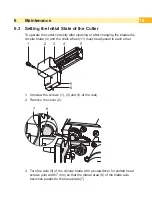
Page 19: ...the circular blade 4 and the clock wheel 11 must be adjusted to each other 2 1 3 4 5 6 6 1 Unscrew the screws 1 3 and 6 at the rear 2 Remove the cover 2 7 8 3 Turn the axle 5 of the circular blade wit...

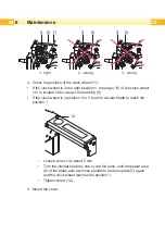
Page 20: ...ted in the area of the marking 9 If the clock wheel is in position 2 or 3 turn the circular blade to reach the position 1 12 Loosen screw 12 about 5 mm Turn the circular blade by one or two full turns...

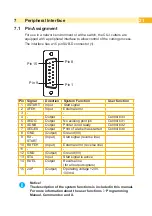
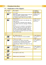
Page 21: ...l bit 3 5 XEDG Output No existing print job Control bit 1 6 XDNB Output Printer is not ready Control bit 2 7 XEGES Output Print of a label has started Control bit 0 8 GND Output Ground 0V 9 RX START I...

Page 22: ...job will continue The last label printed before the error occurred will be repeated Pressing the cancel key will stop the print job and the printer will be reset Switch on 24 V between Pin 2 and Pin...

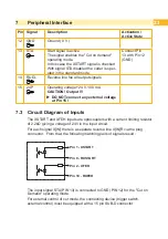
Page 23: ...voltage at Pin 15 7 3 Circuit Diagram of Inputs The XSTART and XFEH inputs are optocouplers with a current limiting resistor of 2 2k giving a voltage of 24V in the input circuit For each signal X IN...

Page 24: ...ablished through solid state relays The outputs are connected to one another on one side The common line leads to the plug connector as a RUEL signal The switch function of the outputs is to open or c...

Page 25: ...OTE This equipment has been tested and found to comply with the limits for a Class A digital device pursuant to Part 15 of the FCC Rules These limits are designed to provide reasonable protection agai...

Page 26: ...26 26 This page was intentionally left blank...

Reviews: