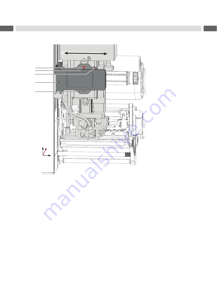
background image

20

20

6.1.3 

Moving the Pad in X-Direction

y

x

z

1
2
3

5

4

Fig. 16 

Displacement in the Y direction

Displacement in the X direction (Side) 

1.  Loosen screw (3) on the binder (5).

2.  Move cylinder assembly with the pad along the crossbeam (4) so that the dispensed label is aligned centrally to 

the pad. As reference use the provided graduation/ruler on the crossbeam. 
Orientation: Graduation (2) and Marking (1)

3.  Tighten  screw (3).

6 Adjustments

Summary of Contents for 4414 Series

Page 1: ...Service Manual 4414 MADE IN GERMANY Stroke Applicator...

Page 2: ...duct can occur Please check www cab de for the latest update Terms and conditions Deliveries and performances are effected under the General conditions of sale of cab Service Manual for the following...

Page 3: ...in X Direction 20 6 2 Set Throttle Valves on the Cylinders 21 6 3 Set the Sensors 21 6 4 Vacuum Adjustments 22 6 5 Blow Tube Support Air Adjustments 23 6 6 Labelling Position of the Tamp 24 6 7 Adjust...

Page 4: ...to life and limb of the user or third parties and or damage to the device and other tangible assets can arise during use The device may only be used for its intended purpose and if it is in perfect wo...

Page 5: ...onic modules or their software can cause malfunctions Other unauthorized work on or modifications to the device can also endanger operational safety Always have service work done by a qualified worksh...

Page 6: ...58 HERMES Q4 10 114 10 114 10 114 Label height in mm for HERMES Q2 4 80 8 80 4 80 HERMES Q4 8 80 8 80 8 80 Compressed air pressure 0 45 MPa 4 5 bar Sound pressure level under 74 dB A Product during l...

Page 7: ...printer 5 Compressed air connector 6 Shutoff valve 7 Setting screw for vertical adjustment cylinder assembly 8 Throttle valve cylinder move out Z direction 9 Screw to fix the vertical tamp position 10...

Page 8: ...17 Sensor Start Position 18 Locking for hinges 19 Interface to the printer 20 Sensor labeling position 21 Pad customized 22 Valve Cylinder Z 23 Valve Cylinder X Y 24 Valve Blow air 25 Valve Vacuum and...

Page 9: ...ad as ordered 5 Documentation Fig 5 Contents of delivery i Note Please keep the original packaging in case the applicator must be returned Attention The device and printing materials will be damaged b...

Page 10: ...initiated The processed labels have to be removed manually After a few seconds the printer carries out a short backfeed to position the front edge of the next label at the printing line i Note This sy...

Page 11: ...her alignment elements This will enable use of the applicator directly after cleaning Pivot Away Dismount the applicator 1 Loosen thumbscrew 5 and swing the applicator away 2 Disconnect SUB D 15 male...

Page 12: ...al Upper position not left There has been no change of the switch state at the upper sensor at the cylinder between the start of the labelling process and the signal from the labelling position sensor...

Page 13: ...6472 54x35 5 Pressure value of the compressed air 0 45 MPa 4 5 bar Factory setting sensors Cylinder Z 6 8 Lift Speed of Cylinder Z Cylinder X Y 6 13 Sensors on Cylinder X Y Factory settings throttle v...

Page 14: ...fix cover 2 Fig 8 Cover 5 4 Transportation Lock 1 3 2 1 3 2 4 3 Fig 9 Stopper as transport lock When the applicator is delivered the stopper 2 is mounted on the rod 1 With this stopper 2 the labellin...

Page 15: ...to the printer and tighten the thumbscrew 5 5 Keep the external compressed air supply closed and close the shut off valve 10 on the applicator see illustration 6 Insert external compressed air supply...

Page 16: ...ollisions of the pad with other parts of the printer applicator system please roughly align the pad in all directions 6 Adjustments before connecting the applicator to the compressed air supply 5 7 Mo...

Page 17: ...n the pad 4 3 1 2 A B 5 6 y x z Fig 13 Aligning the pad to the dispensing plate 1 Loosen the knurled screw 3 and the set screw 4 2 Screw in the knurled screw 3 until the pad edges 5 are aligned parall...

Page 18: ...cylinder extends by spring force and is in the label transfer position 2 Loosen screws 1 on the cross beam 2 3 Move cylinder assembly 4 with the pad and crossbeam 2 along the guiding rail 3 that the d...

Page 19: ...the throttle valve 4 The cylinder extends by spring force and is in the label transfer position 1 Loosen screw 3 on the binder 2 2 Turn the setting screw 1 so that the bottom side of the pad is 1 mm o...

Page 20: ...n the X direction Side 1 Loosen screw 3 on the binder 5 2 Move cylinder assembly with the pad along the crossbeam 4 so that the dispensed label is aligned centrally to the pad As reference use the pro...

Page 21: ...Cylinder Z 6 7 Lift Speed of Cylinder Z Cylinder Y 6 12 Lift Speed of Cylinder Y 6 3 Set the Sensors Sensors are used for status detection and process control on the applicator Precise positioning is...

Page 22: ...up over the entire area X To increase the vacuum turn the setting screw on the throttle valve 1 counterclockwise Measuring Point Vacuum MP V MP V 1 2 3 Use a manometer with a measurement range of 7 t...

Page 23: ...n the direction that the air current can support the take up of the label For small labels direct the air current to the dispensing edge 4 of the printer For larger labels direct the air current away...

Page 24: ...t it on support air throttle valve support air 4 Mount cover again Fig 23 Reading points to measure the pressure Attention After pressure measurements connect all component exactly and check it 6 6 La...

Page 25: ...Loosen the screw 2 in the stopper 1 i Note In case you move the tamp assembly manually move in the Y cylinder So that the tamp doesn t touch the dispense plate or blow tube during movement 4 Move the...

Page 26: ...d speed turn screw 2 at the upper valve 1 counterclockwise i Note The application pressure of the pad is mainly depending on the downward speed of the pad X In order to reduce the application pressure...

Page 27: ...tension of the spring in the adapter bolt is set in order to avoid unintentional triggering of the sensor End Position 6 The triggering magnet is integrated in the adapter bolt and varies its positio...

Page 28: ...the applicator is operated at higher cylinder speeds and with larger pads Adjustments like chapter 6 5 Adjustment of the Stopper for Blow Mode Adjust the stopper with maximum compressed spring Fig 31...

Page 29: ...counterclockwise turning clockwise on throttle valve 3 reduced the speed move in in Y direction 6 13 Sensors on Cylinder X Y 3 4 z x y 11 mm 1 7 mm 2 1 Place sensor start position 2 cylinder X so tha...

Page 30: ...ew 1 and dismount the stamp 2 to get to the locking washer 6 3 4 5 6 Fig 36 Loosening the adapter bolt X Push the adapter bolt 3 into the stamp uptake 4 to ensure that the bottom of the bolt is pushed...

Page 31: ...labelling cycle Stamp on Blow on Print Apply x x Apply Print Waiting position up x x Apply Print Waiting position down x Table 3 Operation and application modes Additionally all operating modes can b...

Page 32: ...he label and consequently avoids faults when the label is being picked up from the printer 0 ms Support delay off Setting the switch off delay max 2 5 s for the supporting air between the end of label...

Page 33: ...ng cycles by alternately pressing the button and Enter button 8 1 Test Mode without a Print Job X In the submenu Labelling Peel off position adjust the Peel off position in such a way that the blank l...

Page 34: ...ter configuration to find the best peel off offset for the initiation 8 2 Test Mode with a Print Job This method allows testing of the labeling process with actual printing data by using the button X...

Page 35: ...1 Cylinder X CON 2 CON 1 CON 21 CON 22 CON 3 CON 11 CON 12 34 Valve Block CON 1 54 Applicator Control CON 1 50 Sensor Labeling Position Cylinder Z 49 Sensor Start Position Cylinder Z 44 SUB D 9 Interf...

Page 36: ...36 36 9 Drawings 9 2 Pneumatic drawing Type 4414 Fig 40 Pneumatics Type 4414...

Page 37: ...37 9 Drawings 9 3 Label position Type 4414 L Fig 41 Label position 4414L...

Page 38: ...38 38 9 Drawings 9 4 Label position Type 4414 R Fig 42 Label position 4414R...

Page 39: ...Mounting 16 O Operation 11 Overview 8 P Pad 17 19 Pad in X Direction 22 Pad in Y Direction 20 Pad in Z Direction 21 Parameters 34 Peel off Mode 35 Peel Position 35 Pneumatic 38 Print Apply 34 Printer...

Reviews: