


20
20
6.1.1
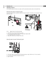
Moving the Pad in Y-Direction
y
x
z
8
1 mm
1 mm
7
y
x
z
6
1
3
2
4
5
Fig. 16
Displacement in the Y direction
Displacement in the Y direction (printing direction)
1.
Switch off the compressed air and pull the tube out of the throttle valve (5). Turn the pad over the dispensing plate
(8) of the printer by hand.
2. Loosen screws (1) on the cross beam (2).
3. Move cylinder assembly (4) with the pad and crossbeam (2) along the guiding rail (3) that the distance from the
edge of the pad (7) to the edge of the dispensing plate (8) of the printer is approximately 1 mm.
Orientation: Graduation (6)
4. Tighten screws (1).
5. Put the tube back into the throttle valve (5) and switch on the compressed air.
Summary of Contents for 4214 Series
Page 1: ...Service Manual 4214 MADE IN GERMANY Stroke Turn Applicator...
Page 39: ...39 9 Drawings 9 2 Pneumatic Drawing Type 4214 Fig 43 Pneumatics type 4214...
Page 40: ...40 40 9 Drawings 9 3 Labeling Position Type 4214 L Fig 44 Labeling position 4214L...
Page 41: ...41 9 Drawings 9 4 Label Position Type 4214 R Fig 45 Labeling position 4214R...


