


7
2.3
Overview Without Cover
1
2
3
4
5
7
8
9
11
10
12
13
14
6
support air
vacuum
15
16
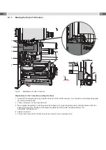
Fig. 2
Device overview - Front view
1 Stopper for the operation mode "Blow on", transport lock
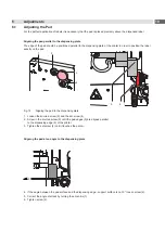
2 Throttle valve cylinder - move in Z-direction
3 Knurled screw for attaching the applicator to the printer
4 Setting screw to adjust the angle between applicator and
printer
5 Compressed air connector
6 Sensors Middle Position Z-direction
7
Shutoff valve
8 Setting screw for vertical adjustment cylinder
assembly
9 Throttle valve
cylinder - move out Z-direction
10 Cylinder R (Rotation)
11 Pad (customized)
12 Throttle valve cylinder R- move in
13 Throttle valve cylinder R- move out
14 Blow tube for supporting air
15 Support air throttle valve
16 Vacuum throttle valve
Front View
Product Description
Throttle valves vacuum / support air
y
x
z
Summary of Contents for 4214 Series
Page 1: ...Service Manual 4214 MADE IN GERMANY Stroke Turn Applicator...
Page 39: ...39 9 Drawings 9 2 Pneumatic Drawing Type 4214 Fig 43 Pneumatics type 4214...
Page 40: ...40 40 9 Drawings 9 3 Labeling Position Type 4214 L Fig 44 Labeling position 4214L...
Page 41: ...41 9 Drawings 9 4 Label Position Type 4214 R Fig 45 Labeling position 4214R...


