background image

Important Safety Information (US) / Belangrijke Veiligheidsinformatie (NL) / Importanti Informazioni Sulla Sicurezza (IT)


Do not plug the unit in any outlet that does not 
have  enough  current  to  allow  the  device  to 
function.    Refer  to  the  specifications  in  this 
manual for power level of the unit.


Liquid:  If  this  unit  or  its  corresponding  power 
adapter has had liquid spilled on or in it, do not 
attempt to use the unit.  Do not attempt to use 
this  product  in  an  outdoor  environment  as 
elements  such  as  rain,  snow,  hail,  etc.  can 
damage the product.


In  case  of  a  storm,  it  is  recommended  that  you 
unplug this device from the outlet.


Avoid  placing  this  product  next  to  objects  that 
produce  heat  such  as  portable  heaters,  space 
heaters, or heating ducts. 


THERE  ARE  NO  USER  SERVICEABLE  PARTS.    Do 
not attempt to open this product and expose the 
internal circuitry.  If you feel that the product is 
defective,  unplug  the  unit  and  refer  to  the 
warranty information section of this manual. 


Steek het apparaat in een stopcontact dat niet 
genoeg stroom om het apparaat te laten 
functioneren. Raadpleeg de specificaties in deze 
handleiding om de macht niveau van de 
eenheid.


Vloeistof: Als dit apparaat en het bijbehorende 
adapter Er vloeistof gemorst op of in het, 
probeer dan niet om het apparaat te gebruiken. 
Probeer niet om dit product te gebruiken in de 
buitenlucht als elementen zoals regen, sneeuw, 
hagel, enz. kunnen het product beschadigen.


In het geval van een storm, is het raadzaam dat 
u dit apparaat de stekker uit het stopcontact.


Vermijd het plaatsen van dit product naast 
objecten die warmte produceren, zoals 
draagbare kachels, kachels, of 
verwarmingsleidingen.


ER ZIJN GEEN ONDERDELEN. Probeer niet om dit 
product te openen en de interne circuits bloot te 
leggen. Als u denkt dat het product defect is, 
haalt u de eenheid en raadpleegt u de garantie

-

informatie van deze handleiding. 


Non collegare l'unità in una presa che non ha ab-
bastanza corrente per consentire al dispositivo di 
funzionare. Fare riferimento alle specifiche in 
questo manuale per il livello di alimentazione 
dell'unità.


Liquido: Se l'apparecchio o il relativo adattatore di 
alimentazione è stato versato del liquido sopra o 
dentro, non tentare di utilizzare l'unità. Non ten-
tare di utilizzare il prodotto in un ambiente esterno 
come elementi quali pioggia, neve, grandine, ecc 
possono danneggiare il prodotto.


In caso di maltempo, si consiglia di scollegare il 
dispositivo dalla presa di corrente.


Evitare di collocare il prodotto vicino a oggetti che 
producono calore, come stufe portatili, stufe o 
condotti di riscaldamento.


NON CI SONO parti riparabili dall'utente. Non 
tentare di aprire il prodotto ed esporre la circuit-
eria interna. Se si ritiene che il prodotto è difetto-
so, scollegare l'unità e consultare la sezione In-
formazioni sulla garanzia del presente manuale. 


57


Summary of Contents for 29510

Page 1: ...r Cat5e Certifi HDBaseT ES Extensor 4K HDMI y USB sobre Cat5e Certificado HDBaseT NL 4K HDMI en USB Over Cat5 Extender HDBaseT Gecertificeerd IT Extender per HDMI 4K e USB su Cat5 Certificato HDBaseT...

Page 2: ...iguration 29 IR Sensor Installation 30 Mounting Bracket Installation 31 Technical Specifications 32 Important Safety Information 57 C2G Warranty 59 Einf rung 4 Produktschaubild 49 50 Ger teinstallatio...

Page 3: ...ciel RJ11 pour les mises jour de micrologiciel uniquement C ble RJ11 pour l extension s rie Adaptateur RJ11 vers DB9 pour les mises jour de micrologiciel et l extension s rie Support de fixation mural...

Page 4: ...kershandleiding RJ11 Firmware Update Kabel alleen voor updaten van firmware RJ11 Kabel voor seri le extensie RJ11 naar DB9 Adapter voor zowel up daten van firmware als seri le extensie Muurbeugel Voet...

Page 5: ...Sender IR Verl ngerungssatz 1x Sender und 1x Empf nger Bedienungsanleitung RJ11 Firmware Updatekabel nur f r Firm ware Aktualisierung RJ11 Kabel f r serielle Verl ngerung RJ11 DB9 Adapter f r Firmware...

Page 6: ...Product Diagram US 5 Transmitter Receiver...

Page 7: ...l device using a RJ11 serial cable for serial extension or Connect to a PC using a RJ11 firmware update cable for firmware update R6 Connect to a serial device using a RJ11 serial cable for serial ext...

Page 8: ...eiver to the port labeled IR OUT on the receiver unit Otherwise connect the supplied IR transceiver to the port labeled IR OUT on the transmitter unit then connect the supplied IR receiver to the port...

Page 9: ...n RJ11 extension cable RJ11 to DB9 adapter for connecting the Transmitter and Receiver in between the DCE data communication equipment and DTE data terminal equipment The configuration of controller s...

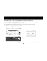
Page 10: ...nt the IR sensor with the multi mode stand IR Sensor Installation You can distinguish the IR transceiver and IR receiver from the different icons by referring to above the photos To control a display...

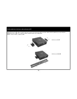
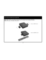
Page 11: ...the display device Step 2 Mount the L brackets to both sides of the unit using the provided screws Step 3 Secure the L brackets to the flat Support items 98174 Replacement power supply 98175 Replacem...

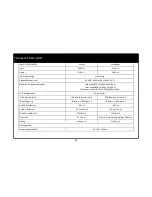
Page 12: ...DID Video Configuration EDID Audio Configuration Auto USB 2 0 Interface USB Mini B Female x 1 Host USB A Female x 4 Devices IR Extension IR Input x 1 IR Output x 1 IR Input x 1 IR Output x 1 Serial In...

Page 13: ...Diagramme du produit FR 12 metteur R cepteur...

Page 14: ...dinateur avec un c ble de mise jour de micrologiciel RJ11 pour les mises jour de micrologiciel R6 connecter un p riph rique s rie avec un c ble s rie RJ11 pour l extension s rie ou connecter un ordina...

Page 15: ...necter le transmetteur IR fourni au port IR OUT sur le r cepteur Sinon connecter le transmetteur IR fourni au port IR OUT sur l metteur puis connecter le r cepteur IR fourni au port IR IN sur le r cep...

Page 16: ...teur RJ11 vers DB9 fournis pour connecter l metteur et le r cepteur entre l ETCD quipement de terminaison de circuit de donn es ou DCE et l ETTD quipement terminal de traitement de donn es ou DTE Si v...

Page 17: ...aque m tallique aimant e pour le montage du capteur IR avec le socle multimode Installation du capteur IR Vous pouvez diff rencier le transmetteur IR et le r cepteur IR avec leurs ic nes en vous repor...

Page 18: ...c est dire au dos du p riph rique d affichage tape 2 fixer les supports en L des deux c t s du dispositif l aide des vis fournies tape 3 fixer les supports en L sur le support plat Installation du su...

Page 19: ...rin 1920 x 1080 60 Hz 100 m Configuration EDID automatique Interface USB 2 0 USB Mini B femelle h te USB A femelle x 4 p riph riques Extension IR Entr e IR x1 Sortie IR x1 Entr e IR x1 Sortie IR x1 In...

Page 20: ...Diagrama del product ES 19 Unidad de transmisi n Unidad de recepci n...

Page 21: ...ble RJ11 de actualizaci n de firmware para la actualizaci n de firmware R6 Conectar a un dispositivo serie usando un cable serie RJ11 para la extensi n serie o Conectar a un PC utilizando un cable RJ1...

Page 22: ...OUT en la unidad de recepci n De otro modo conecte el transceptor IR suministrado al puerto denominado IR OUT en la unidad de transmisi n despu s conecte el receptor IR suministrado al puerto denomin...

Page 23: ...6 pines suministrado y el adaptador RJ11 a DB9 para conectar el transmisor y el receptor entre el DCE equipo de comunicaci n de datos y el DTE equipo terminal de datos Si no dispone de un conector se...

Page 24: ...on el soporte multimodo Instalaci n del sensor IR Puede distinguir el transceptor IR y el receptor IR mediante los diferentes iconos haciendo referencia sobre las fotos Para controlar una pantalla o d...

Page 25: ...en la parte posterior del dispositivo de pantalla Paso 2 Monte los soportes en L a ambos lados de la unidad utilizando los tornillos proporcionados Paso 3 Asegure los soportes en L a la parte plana In...

Page 26: ...080 60 Hz 100 m configuraci n EDID Autoconfiguraci n interfaz USB 2 0 USB USB mini B hembra host USB A hembra x 4 dispositivos IR extensi n IR 1x salida IR 1x entrada IR 1x salida IR 1x entrada interf...

Page 27: ...Product Diagram UK 26 Transmitter unit Receiver unit...

Page 28: ...ect to a serial device using an RJ11 serial cable for serial extension or Connect to a PC using an RJ11 firmware update cable for firmware update R6 Connect to a serial device using an RJ11 serial cab...

Page 29: ...the port labelled IR OUT on the receiver unit Otherwise connect the supplied IR transceiver to the port labelled IR OUT on the transmitter unit then connect the supplied IR receiver to the port label...

Page 30: ...need to use the supplied 6 pin RJ11 extension cable and RJ11 to DB9 adaptor for connecting the transmitter and receiver between the DCE data communication equipment and DTE data terminal equipment If...

Page 31: ...nt the IR sensor with the multi mode stand IR Sensor Installation You can distinguish the IR transceiver and IR receiver from the different icons by referring to above the photos To control a display...

Page 32: ...he unit will be mounted i e the back of the display device Step 2 Mount the L brackets to both sides of the unit using the screws provided Step 3 Secure the L brackets to the flat surface Mounting Bra...

Page 33: ...DID Video Configuration EDID Audio Configuration Auto USB 2 0 Interface USB Mini B Female x 1 Host USB A Female x 4 Devices IR Extension IR Input x 1 IR Output x 1 IR Input x 1 IR Output x 1 Serial In...

Page 34: ...Productschema NL 33 Zender Ontvanger...

Page 35: ...n RJ11 seri le kabel voor seri le extensie of Aansluiten op een PC gebruik een RJ11 firmware update kabel voor firmware update R6 Aansluiten op serieel toestel gebruik een RJ11 seri le kabel voor seri...

Page 36: ...an een brontoestel indien noodzakelijk Stap 5 Sluit een geleverde RJ11 naar DB9 adapter aan op een geleverde RJ11 seri le verlengkabel sluit de RJ11 connector van de RJ11 seri le aansluitingskabel aan...

Page 37: ...oor het aansluiten op de poort TOSLINK OUT op de ontvanger de TOSLINK ingangspoort van een scherm of een TOSLINK brontoestel indien noodzakelijk Stap 5 Sluit een geleverde RJ11 naar DB9 adapter aan op...

Page 38: ...RJ11 verlengkabel RJ11 naar DB9 adapter voor het aansluiten van de zender en ontvanger tussen de DCE data communicatie equipment en DTE data terminal equipment Indien uw computer geen seri le connecto...

Page 39: ...metalen plaat voor het bevestigen van de IR sensor met de multimodus stand IR Sensor installatie U kunt de IR transceiver en de IR ontvanger onderscheiden door de verschillende pictogrammen kijk in bo...

Page 40: ...den d w z de achterkant van het schermtoestel Stap 2 Bevestig de L beugels aan beide kanten van het toestel met behulp van de geleverde schroeven Stap 3 Zet de L beugels vast op de platte kant Install...

Page 41: ...0 30Hz 90m Cat5e or Cat6 Solid 1920 x 1080 60Hz 100m EDID Configuratie Auto USB 2 0 Interface USB Mini B vrouwelijk Host USB A vrouwelijk x 4 Toestellen IR Extensie IR Ingang x1 IR Uitgang x1 IR Ingan...

Page 42: ...Diagramma del prodotto IT 41 metteur R cepteur...

Page 43: ...RJ11 per l estensione di serie o connettersi a un PC utilizzando un cavo RJ11 per l aggiornamento del firmware R6 Collegare a un dispositivo seriale tramite un cavo seriale RJ11 per l estensione di se...

Page 44: ...uscita TOSLINK di un dispositivo sorgente se necessario Fase 5 Collegare un adattatore da RJ11 a DB9 in dotazione a un cavo di prolunga seriale RJ11 in dotazione collegare il connettore RJ11 del cavo...

Page 45: ...INK per collegare la porta etichettata come TOSLINK OUT del ricevitore e la porta di ingresso TOSLINK di un dispositivo sorgente TOSLINK Se necessario Fase 5 Collegare un adattatore da RJ11 a DB9 in d...

Page 46: ...rolunga a 6 pin RJ11 in dotazione e l adattatore da RJ11 a DB9 per il collegamento di trasmettitore e ricevitore tra DCE data communication equipment e DTE Data Terminal Equipment Se non c il connetto...

Page 47: ...re il sensore IR sullo stand Installazione sensore IR possibile distinguere il trasmettitore IR e il ricevitore IR dalle diverse icone facendo riferimento alle foto sopra Per controllare un monitor o...

Page 48: ...io nella parte posteriore del dispositivo di visualizzazione Fase 2 Montare le staffe a L su entrambi i lati dell unit utilizzando le viti in dotazione Fase 3 Fissare le staffe a L su quella piatta In...

Page 49: ...at6 solido 1920 x 1080 60 Hz a 100 m Configurazione EDID automatica USB 2 0 Interfaccia USB mini B femma Host USB A femmina x 4 dispositivi Estensione IR Ingresso IR x1 Uscita IR x1 Ingresso IR x1 Usc...

Page 50: ...Produktschaubild DE 49 metteur R cepteur...

Page 51: ...ielle Verl ngerung oder Anschluss an einen PC Verwendung eines Firmware Updatekabels RJ11 zwecks Firmware Aktualisierung R6 Anschluss an serielles Ger t Verwendung eines seriellen Kabels RJ11 f r seri...

Page 52: ...NK Kabel soweit erforderlich Schritt 5 Verbinden Sie einen mitgelieferten RJ11 DB9 Adapter mit einem mitgelieferten seriellen Verl ngerungskabel RJ11 Schlie en Sie den RJ11 Verbinder des seriellen Ver...

Page 53: ...T am Empf nger gekennzeichneten Port und den TOSLINK Input Port eines Displays oder eines TOSLINK Queller ts mit einem TOSLINK Kabel soweit erforderlich Schritt 5 Verbinden Sie einen mitgelieferten RJ...

Page 54: ...hspolige Verl ngerungskabel und den RJ11 DB9 Adapter zum Anschluss von Sender und Empf nger zwischen der D E Daten bertragungseinrichtung und der DEE Datenendeinrichtung benutzen Verf gt Ihr Computer...

Page 55: ...v k nnen Sie anstatt der magnetischen Metallplatte die mitgelieferten Schrauben benutzen um den IR Sensor am Mehrmodus St nder zu befestigen IR Sensor Schritt 1 F hren Sie den Stecker des IR Sensors d...

Page 56: ...seite des Displayger ts Schritt 2 Bringen Sie die L Halterungen an beiden Seiten der Einheit an und benutzen Sie dazu die mitgelieferten Schrauben Schritt 3 Sichern Sie die L Halterungen an der flache...

Page 57: ...e oder Cat6 Solid 1920 x 1080 60Hz 100 m EDID Konfiguration Automatische USB 2 0 Schnittstelle USB Mini B Buchse Host USB A Buchse x 4 Ger te IR Verl ngerung IR Input x 1 IR Output x 1 IR Input x 1 IR...

Page 58: ...ct te gebruiken in de buitenlucht als elementen zoals regen sneeuw hagel enz kunnen het product beschadigen In het geval van een storm is het raadzaam dat u dit apparaat de stekker uit het stopcontact...

Page 59: ...lla no intente utilizar la unidad No intente utilizar este producto en un entorno al aire libre como elementos tales como lluvia nieve granizo etc puede da ar el producto En caso de tormenta se recomi...

Page 60: ...reso RMA Return Merchandise Authorization contattare il servizio di assistenza al numero 0800 328 2916 o visitare il sito web www c2g com uk Wir bei C2Gm chten dass Sie mit Ihrem Kauf vollst ndig zuf...

Page 61: ...Notes US Remarquer FR Notas ES Notizen DE 60...

Page 62: ...with the instructions may cause harmful interference to radio communications However there is no guarantee that interference will not occur in a particular installation If this equipment does cause ha...

Reviews: