8
2)
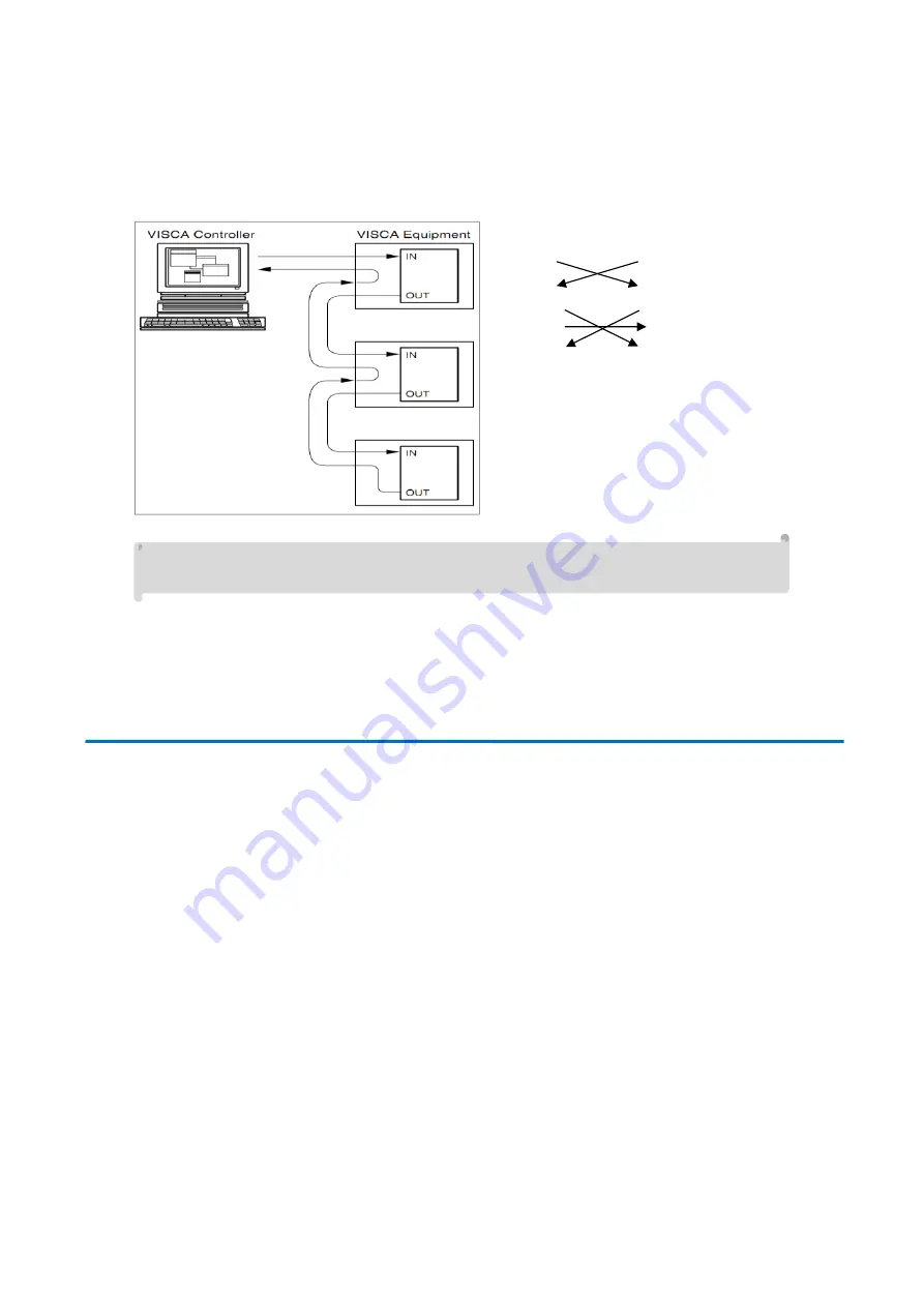
VISCA networking as shown below:
Camera cascade connection method
Camera 1
Camera 2
1.DTR
1.DTR
2.DSR
2.DSR
3.TXD
3.TXD
4.GND
4.GND
5.RXD
5.RXD
6.GND
6.GND
7.IR OUT
7.OPEN
8. NC
8.OPEN
Note: Has RS232 input and output interface allowing for cascading inputs.
3.
Operating
Instruction
s
3.1 Video Output
3.1.1 Power-On Initial Configuration
After connecting the power, the camera will initiate self-test mode. The IR indicator light will start flashing. When the camera returns
to the HOME position (middle position for P/T) and lens finishes zoom in/out, the self-testing is finished. The IR led will stop flashing. If
the preset 0 is set, the camera will rotate to the (0) preset position after initial configuration.
3.1.2 Video Output
Connect the video output cable; this may vary based on camera model and application.
Figure 1.4.1 is for your reference (output interface introduction for each product)
1)
NDI Network Output: Connect this product and your computer via network cable. Open the browser and enter the camera IP
address (factory default 192.168.5.163) in the address bar. On the login page enter username and password - factory default
is “admin” for both. Once logged in you will be prompted to download and/or enable manage the plugin, click allow and video
will be displayed.
(Note: If you forget your username, password, IP address, you can manually restore the default by the remote controller key
combination * #)
2)
3G-SDI output or DVI (HDMI) output: Connect the monitor with the corresponding video output interface and the image will
be displayed after initial power-on.


