background image


- 14 - 

4. Maintenance and Repair 


Important

Before executing maintenance and repair works, always first unplug from the mains!


During the operation of the ball machine, make sure that no small parts (for example hairs, in-
dented balls, etc.) get into the collection net and thus into the machine, because they can lead to 
ball jams.


The ball shooting discs are very durable (at least 500 hours). Nevertheless, these discs will finally wear 
off after intense use. One sign for a worn disc is that the machine releases the balls at irregular lengths at 
high speed. This means that the surface of the discs does not have enough grip on the balls. For that rea-
son, the distance of the discs has to be adjusted. 


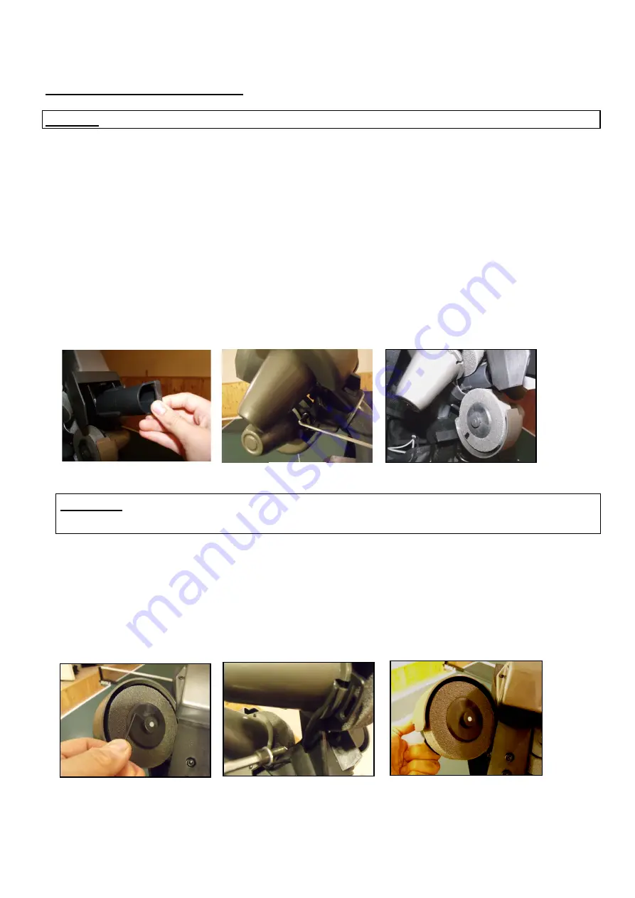
Put the plastic adjusting tube in the release hole found between the discs 

(Fig. 13.)

. Loosen first, for ex-

ample, the black imbus “adjusting” screw near the cover- with the bigger allan key found among the ac-
cessories - of he lower motor 

(Fig. 14.)

 and turn up the motor (gripping its cover) towards the adjusting 

tube until the disc touches it. 

(Fig. 15.)

 Do all this also with the other two motors.  


Please note

The correct distance is 35-36 mm. This is the diameter of the adjusting tube. The release 

mechanism functions perfectly up to a distance of 37-38 mm

.


When  the  distance  cannot  be  adjusted  anymore,  the  ball  throw  discs  have  to  be  replaced.  Therefore 
loosen the screws 

(Fig.16.)

 found in the plastic disc holders – with the smaller allan key found among 

the  accessories  -  (regarding  all  3  discs),  then  remove  the  “adjusting  screws”  found  at  the  two  upper 
motors (it is not enough only to loosen those) 

(Fig. 17.)

 Then totally turn up the two upper motors grip-

ping  their  casings  and  turning  those  away  from  the  throwing  hole  in  order  to  make  possible  the  pull 
down of the throw discs from the shafts of the motors. 

(Fig. 18.)


Fig. 12. 


Fig. 13. 


Fig. 16. 


Fig. 15. 


Fig. 16. 


Fig. 13. 


Fig. 14. 


Fig. 15. 


Fig. 17. 


Fig. 18. 


Fig. 17. 


Fig. 18. 


Summary of Contents for PowerPong 3000

Page 1: ...Table Tennis Robot PowerPong 3000 5000 developed by Csaba Lukács Operation Manual Œ certificated ...

Page 2: ...eplacement parts starting with the date of purchase Please keep your receipt World novelty A unique head with 3 discs Discs made of tough foam with a special coating for longevity Compact solid functional workmanship built together with a big collecting net 6 kg Well thought out and easy to use control panel Programmed and random throwing of balls with different spin speed direction and trajectory...

Page 3: ...e coaxial DC plug of the adapter close near the 15 pole connector finally connect one end the smaller connector of the extension cord in the 26 pole connector found under the 15 pole one Fig 2 Attention Connect the cables very carefully because the pins could get wraped twisted very easily 3 Turn down the net keeping poles until the first collision then turn out the hanging poles used for hang ing...

Page 4: ...stic corner elements found on the ends of the net keeping poles exactly to the corners of the table how you can see below Fig 6 Please note There can be found sticker velcros on the inner surfaces of the plastic corner elements When the companion pieces found among the other belongings are put on the corners of the table then the net can be fixed more stable to the table 6 Then pull the end of the...

Page 5: ... line Buttons for setting the sidespin and LED line Ball sidespin level setting and feedback Buttons for setting the speed and LED line Ball speed level setting and feedback Buttons for setting the spin and LED line Ball spin level setting and feedback Stop Start button and sign LED see remote Pushing it the root gets in stop setting position switch red light is on The actual ball can be set Selec...

Page 6: ...efine the following elements in order to set the PowerPong 3000 3001 easier The features of the thrown balls When setting the balls it is necessary to set the type and the place of the balls which parameters are defined by the following parameters a Spin side spin b Speed Ball type c Trajectory the height of the shot d Right left placing Ball placing One type ball given to one point The Ball min b...

Page 7: ... machine doesn t throw anymore the set balls in their set order but in random way jumping here and there among the assigned balls Therefore it can not be foreseen where the robot throws the next ball It is sure only the fact that the balls are thrown to one of the set places It needs at least 2 assigned balls to use this function Combining Trnd and rnd The Trnd and rnd functions can be combined by...

Page 8: ...hanged of course and in case the spin of the balls in the rally is the same for each then using the Spin button also the spin of all the balls in the rally can be changed simultaneously If the spins of the set balls are differ ent then this function is not available The buttons for setting the values function during the play only in one push one step Rallies with service The designation of the 1 a...

Page 9: ...d and it will be saved there with pushing the Save button Please note All the set values and characteristics can be saved in the memory except the ran dom and the cycle functions These features can be activated during the play without any limit Playing and changing the rallies saved in the BASE memory It is possible to get into memory function at any time even during play with pushing the Mem t bu...

Page 10: ...ecome continuous In order that the cells of the cluster to be distinguished from the ones of the cells of the Base memory The cluster cells are signed with number dot number dot for example the 23 cell is signed with 2 3 7 You can get back to the Base memory with pushing again the Mem t and the procedure is repeated from point 2 8 If you want to check what is in the Cluster then you simply start t...

Page 11: ...leting the whole Cluster With pushing two times the Mem t button the Clust LED lights and the C0 cluster number appears on the display You can choose the cluster that you want to delete and you can delete all the cells of the cluster at the same time with pushing the Clear button for long Deleting rallies from the Cluster You step in the Cluster memory You choose that group C0 C9 from where you wa...

Page 12: ...played with pushing this Start stop button in a way that with each push the robot throws one ball 2 In case the Ball min button is not in 0 position then it works as the Start stop button works on the control panel Pushing it once the rally starts and it is played until the remote switch is pushed again 3 The round grey Sample button works like the sample button found on the control panel with the...

Page 13: ...inally adjust the desired height in a way that one of the silver signs found on the thinner internal tube to the top margin of external thicker tube then tighten the hand screw Turning the PowerPong 3000 off and Putting out of Service 1 Pull the adapter from current when going out from the place where the machine works Do not let the robot switched on without control 2 If the robot is taken tempor...

Page 14: ...us adjusting screw near the cover with the bigger allan key found among the ac cessories of he lower motor Fig 14 and turn up the motor gripping its cover towards the adjusting tube until the disc touches it Fig 15 Do all this also with the other two motors Please note The correct distance is 35 36 mm This is the diameter of the adjusting tube The release mechanism functions perfectly up to a dist...

Page 15: ... and the three throwing motors jam for any reason the machine stops in self defence Then the fault signal is the following all the 6 yellow lights start to flash on the control box You have no other choice than to take out the head from the machine and take out the offending balls from the bottom part of the robot with the help of a pencil or screwdriver etc through the cleaning hole found there F...

Page 16: ...be activated green indicator light can not be switched on At least two balls must be activated at least two yellow indicator lights must glow see page 7 Ball gets stuck between ball throw discs The yellow light flash on the control unit Pull out the adapter from current remove ball from it between the shooting discs adjust the Ball min button to 0 position then start the play again Attention If yo...

Page 17: ...est was done for the electrical adpter device of conformity a Low Voltage directive 73 23 EEC as last amended by EEC Directive 93 68 EEC Registration No AN 50091861 0001 Report No 17004848 001 as is apparent from Test Report No NTEK 2010NT1115351E and NTEK 2010NT1115353SS The robot PowerPong 3000 is permitted to bear the CE trademark Manufacturer LCS Kft Hungary 2100 Gödöllő Ibolya u 50 e mail lcs...

Reviews: