background image

23

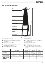
C. Table of injector

   The hose and regulator assembly (NOT INCLUDED) must conform to local standard codes.

   Regulator outlet pressure should meet the corresponding appliance category in B. Specification.

   The appliance requires approved hose in 0.6m length.

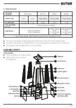
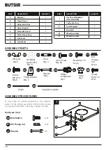
ASSEMBLY PARTS

Tools needed:

   Philips screwdriver w/ medium blade

   Spray bottle of soap solution 

for leakage test

APPLIANCE 

CATEGORY

I

3+(28-30/37)

I

3B/P(30)

I

3B/P(50)

I

3B/P(37)

TYPES OF GAS

Butane

Propane

Butane, propane

or their mixtures

Butane, propane

or their mixtures

Butane, propane

or their mixtures

GAS PRESSURE

28-30 mbar

37 mbar

30 mbar

50 mbar

37 mbar

TOTAL HEAT INPUT

(Hs): (Qn)

13 kW (G30: 945 g/h; G31: 929 g/h)

INJECTOR SIZE:

1.88 mm for main burner

0.18 mm for pilot burner

1.55 mm for main 

burner

0.18 mm for pilot 

burner

1.65 mm for main 

burner

0.18 mm for pilot 

burner

The marking, for example, 1.88 on the injector indicates that the size of injector is 1.88mm

CEILING

W

A

L

L

100 cm

100 cm

lgniter

2270 mm

900 mm

650 mm

730 mm

A

B

C

D

E

F

G

H

L

K

J

I

M

N

Control Box Assy

Lower Support

Block Belt

Wheel Assembly

Bottom

Reflector

Flame Screen

Glass Tube

Upper Support

Protective Guard

Black Silicone Ring

Side Panel

Front Panel

Gas Hose & Regulator 
(NOT INCLUDED)

Summary of Contents for PIRAMIDE

Page 1: ...N E E SDE GARANT I E 0063 1960 MANUAL DE INSTRUCCIONES ESTUFA INSTRUCTION MANUAL HEATER MANUAL DE INSTRU ES FOG O PIR MIDE Guardar el manual para futuras consultas Keep the manual for future reference...

Page 2: ...18 Caution 19 20 Heater Stand and Location 20 Gas Requirements 20 Leakage Test 20 Operation and Storage 21 Cleaning and Care 21 Parts and Specifications 22 Assembly Parts and Procedures 23 24 Problems...

Page 3: ...mal funcionamiento del aparato Lea el manual con atenci n para proceder con la instalaci n uso y mantenimiento antes de instalar o usar el aparato ATENCI N Leer las instrucciones antes de instalar o...

Page 4: ...nguera Si la fuga est en el regulador conexi n de la v lvula de la bombona desconectar vuelva a conectar y realizar otra prueba de fuga Si sigue observando burbujas despu s de varios intentos el regul...

Page 5: ...es Recomendado 100 cm superior y 100 cm lateral m nimo La estufa debe ser ubicada en un suelo firme y a nivel Nunca utilice la estufa en un lugar donde se almacenen combustibles gasolina u otros produ...

Page 6: ...se enciende o se apaga repetir el paso 3 4 Despu s de encender la llama piloto gire el mando de control hasta la posici n de m ximo y mantener durante 5 minutos o m s antes de girar el mando de contro...

Page 7: ...l regulador correspondiente acorde con la presi n de salida mostrada en la siguiente tabla CEILING 100 cm lgniter 2270 mm 900 mm 650 mm 730 mm A B C D E F G H I Sombrerete Tubo de cuarzo Rejilla Sopor...

Page 8: ...sus mezclas PRESI N DE GAS 28 30 mbar 37 mbar 30 mbar 50 mbar 37 mbar POTENCIA CALOR FICA Hs Qn 13 kW G30 945 g h G31 929 g h TAMA O INYECTOR 1 88 mm para quemador principal 0 18 mm para quemador pilo...

Page 9: ...JJ Sujeci n Cdad 4 Llave Cdad 1 HH M6 Tuerca Cdad 4 Tornillo M5 X 12 Cdad 6 LL Pomo Cdad 1 NN OO MM Tornillo M4 X 10 Cdad 1 Cadena Cdad 1 Encendedor Cdad 1 EE FF JJ 1 2 x 4 x 4 x 1 M EE FF AA BB Palo...

Page 10: ...y la base Inserte los pines de la caja de manos en los orificios del soporte superior Presionar para asegurar los pines Utilizar 4 unidades del tornillo 3 16 para asegurar el soporte superior a la ca...

Page 11: ...rtar los 4 soportes superiores en los soportes inferiores Fijar con 8 tornillos 3 16 Materiales Usados Tornillo 3 16 Destornillador 5 Montar la pantalla al soporte superior Fijar la pantalla al soport...

Page 12: ...que el anillo negro de silicona est acoplado en la extremo inferior del tubo como muestra la ilustraci n Deslice el tubo de cuarzo a trav s del orificio del plato inferior y ub quelo en el centro Comp...

Page 13: ...os de los soportes Asegurar las protecciones con las sujeciones usando 4 tornillos 3 16 Materiales Usados Tornillo 3 16 Destornillador Soporte de fijaci n 9 Montar los tres paneles laterales a la estu...

Page 14: ...los orificios de la base inferior Materiales Usados Pomo Tornillo M4 X 10 Cadena Destornillador 11 Conexi n del tubo de goma y el regulador N INCLUIDOS ATENCI N Aseg rese de que el tubo de goma no en...

Page 15: ...nico del fabricante para que la revise No utilice la estufa hasta que la fuga de gas haya sido solventada LISTADO DE PROBLEMAS SOLUCIONES Si el aparato muestra alg n defecto o problema de montaje o us...

Page 16: ...38 12 32 www butsir com E mail info butsir com CERTIFICADO DE GARANT A A RELLENAR POR EL ESTABLECIMIENTOVENDEDOR DESCRIPCCI N DEL APARATO Sello del establecimiento vendedor Marca Modelo Fecha de venta...

Page 17: ...uerdo con el art culo 9 y siguientes de la ley 23 2003 de 10 de julio La presente garant a no cubre BUTSIR no se responsabiliza de los da os que puedan derivarse del mal uso del aparato de su falta de...

Page 18: ...e nance Can cause injury or property damage Read the installation operating and maintenance instruc tions thoroughly before installing or servicing this equipment WARNING Read the instructions before...

Page 19: ...ve is defective and should be returned to cylinder s place of purchase Urn off the gas valve immediately if smell of gas is detected Turn Cylinder Valve OFF If leak is at Hose Do not transport heater...

Page 20: ...proper clearance to non protected combustible materials i e top 100 cm and sides 100 cm minimum Heater must be placed on level firm ground Never operate heater in an explosive atmosphere like in areas...

Page 21: ...ot light or it goes out repeat step 3 4 After the pilot flame lights turn the variable control knob to maximum position and leave it there for 5 minutes or more before turning the knob to desired temp...

Page 22: ...ng the proper regulator according to outlet pressure of regulator as showed in the table below CEILING 100 cm lgniter 2270 mm 900 mm 650 mm 730 mm A B C D E F G H I Reflector Glass Tube Flame Screen L...

Page 23: ...or their mixtures Butane propane or their mixtures GAS PRESSURE 28 30 mbar 37 mbar 30 mbar 50 mbar 37 mbar TOTAL HEAT INPUT Hs Qn 13 kW G30 945 g h G31 929 g h INJECTOR SIZE 1 88 mm for main burner 0...

Page 24: ...g Bracket Qty 4 Wrench Qty 1 HH M6 Flange nut Qty 4 Screw M5 X 12 Qty 6 LL Knob Qty 1 NN OO MM Screw M4 X 10 Qty 1 Chain Qty 1 Long Stem Lighter Qty 1 12 AA BB Palomilla Cdad 3 Arandela 6 Cdad 6 DD EE...

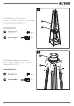
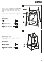
Page 25: ...and base Insert the pins of the control box assy to the holes of upper support press to secure the pins Using 4pcs screw 3 16 screw to secure the upper support and control box assy Hardware Used Scre...

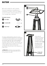
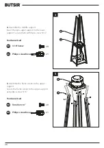
Page 26: ...t the 4pcs upper support to the lower support Secure them with 8pcs screw 3 16 Hardware Used 3 16 Screw Philips screwdriver 5 Assebmle the flame screen to the upper support Secure the flame screen to...

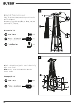
Page 27: ...per plate Ensure the black silicone ring is attached to the lower edge of the glass tube as illustrated Slide the glass tube through the hole of the lower plate cover and onto the middle plate Check a...

Page 28: ...nto the holes in supports Secure the protective guards with fixing brackets with 4pcs 3 16 screws Hardware Used 3 16 Screw Philips screwdriver Fixing Bracket 9 Attach the three side panels to the heat...

Page 29: ...f front panel to the holes of bottom plate Hardware Used Knob Screw M4 X 10 Chain Philips screwdriver 11 Propane Only Proper Hose Connection NOT INCLUDED WARNING Ensure the hose does not contact any h...

Page 30: ...tment and have the patio heater inspected by a certified gas installer If the leak cannot be stopped immediately shut off the gas supply disconnect it and have the patio heater PROBLEMS CHECK LIST If...

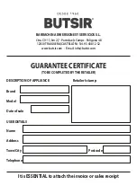
Page 31: ...RA CASTELL N Tel 93 638 12 32 www butsir com E mail info butsir com GUARANTEE CERTIFICATE TO BE COMPLETED BYTHE RETAILER DESCRIPTION OF APPLIANCE Retailer s stamp Brand Model Date of sale USER DETAILS...

Page 32: ...e article was non compliant all in accordance with article 9 and successive articles of Act 23 2003 of 10th July This guarantee does not cover BUTSIR shall not be held liable for any damage caused by...

Page 33: ...u funcionamento do dispositivo Leia atentamente o manual para continuar com a instala o uso e manuten o antes de instalar ou usar o dispositivo ATEN O Leia as instru es antes de instalar ou usar Este...

Page 34: ...ra da mangueira Se o vazamento estiver na conex o regulador v lvula do cilindro desconecte reconecte e execute outro teste de vazamento Se voc continuar a observar bolhas ap s v rias tentativas o regu...

Page 35: ...e os materiais combust veis Recomenda se 100 cm topo e 100 cm lado no m ni mo A estufa deve estar localizada em um terreno plano e firme Nunca use o fog o em um local onde sejam armazenados combus t v...

Page 36: ...do piloto Se a chama do piloto n o ligar ou desligar repita o passo 3 4 Depois de acender a chama do piloto gire o bot o de con trole para a posi o m xima e segure por 5 minutos ou mais antes de girar...

Page 37: ...r correspondente de acordo com a press o indicada na tabela a seguir CEILING 100 cm lgniter 2270 mm 900 mm 650 mm 730 mm A B C D E F G H I Cap Tubo de quartzo Grade Pedaleiro Parte inferior Prote es S...

Page 38: ...s misturas PRESS O DE G S 28 30 mbar 37 mbar 30 mbar 50 mbar 37 mbar POT NCIA DE CALOR Hs Qn 13 kW G30 945 g h G31 929 g h TAMANHO DO BOCAL 1 88 mm para o queimador principal 0 18 mm para o queimador...

Page 39: ...dade 4 FF GG JJ De aperto Qdade 4 Chave Qdade 1 HH M6 Porca Qdade 4 Parafuso M5 X 12 Qdade 6 LL Bot o Qdade 1 NN OO MM Parafuso M4 X 10 Qdade 1 Cadeia Qdade 1 Isqueiro Qdade 1 AA BB Palomilla Cdad 3 A...

Page 40: ...pinos da caixa de m o nos orif cios do suporte superior Pressione para fixar os pinos Use 4 unidades de parafuso de 3 16 para prender o suporte superior caixa de controle Materiais utilizados Parafus...

Page 41: ...nsira os 4 suportes superiores nos suportes inferiores Corrigir com 8 parafusos de 3 16 Materiais utilizados Parafuso 3 16 Chave de fenda 5 Monte a tela no suporte superior Fixe a tela no suporte supe...

Page 42: ...que o anel de silicone preto esteja preso extremidade inferior do tubo conforme mostrado na ilustra o Deslize o tubo de quartzo pelo orif cio da placa inferior e coloque o no centro Verifique se o tu...

Page 43: ...portes Proteja as prote es com os fixadores Usando 4 parafusos de 3 16 Materiais utilizados Parafuso 3 16 Chave de fenda Suporte de fixa o 9 Monte os tr s pain is laterais no fog o usando os parafusos...

Page 44: ...rontal nos orif cios da base inferior Materiais utilizados Bot o Parafuso M4 X 10 Cadeia Chave de fenda 11 Conex o do tubo de borracha e regulador N O INCLU DO CATEN O Certifique se de que o tubo de b...

Page 45: ...ilindro de g s imediatamente desconecte o e entre em contato com o servi o t cnico do fabricante para que cheque N o use o fog o at que o vazamento de g s tenha sido resolvido LISTA DE PROBLEMAS SOLU...

Page 46: ...STELL N Tel 93 638 12 32 www butsir com E mail info butsir com CERTIFICADO DE GARANTIA A PREENCHER PELOVENDEDOR PROPRIEDADE DESCRI O DO APARELHO O selo de vendedor de propriedade Marca Modelo Data de...

Page 47: ...Artigo 9 e seguintes da Lei 23 2003 de 10 de julho Esta garantia n o cobre A BUTSIR n o se responsabiliza por danos que possam surgir do uso incorre to do dispositivo sua falta de manuten o ou sua ma...

Page 48: ...BARRACHINA INVERSIONESY SERVICIOS S L Ctra CV 11 km 2 7 Partida els Camps Pol gono 48 12330TRAIGUERA CASTELL N Tel 93 638 12 32 www butsir com E mail info butsir com...

Reviews: