INSTRUCTION, USE AND
MAINTENANCE MANUAL
Page 19 of 36
GB
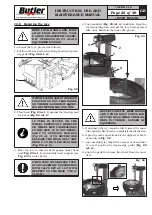
10. When demounting hard tyres, it may happen that
the bead comes onto the mounting tool with the lip
turned. This causes the bead to slide from the lever
when clockwise rotation begins. To avoid this prob-
lem rotate the wheel slightly anti-clockwise until
the bead flattens. Now the clockwise demounting
cycle can begin (See
Fig. 18
).
Fig. 18
NO
YES
If the motor slows down or stops during tyre demount-
ing and mounting, make the following checks:
• check that the bead has been lubricated;
• check that the bead has been pushed into the groove;
• check that the right side of the rim has been chosen
for demounting or mounting the tyre;
• check that the rim groove is not off-centre.
12.6 Setting the tool for tyre fitting and
removal
The tool is locked in position to an hexagon stand
through 4 upper horizontal-axis dowels and a lower
vertical-axis screw. The adjusting clamps lock the tool
in its working position. Adjusting clamps also set head
distance from the wheel rim. Head top is concave for
smoother positioning. For tool setting
a 14” rim with
good concentricity degree and standard profile,
better if with flat upper edge and proper right angle
to its spin axis, is required.
12.6.1 Setting the clamps travel
SET THE CLAMPS BEFORE PO-
SITIONING THE HEAD. AT THIS
STAGE THE HEAD HAS NOT BEEN
SET TO ITS FINAL POSITION YET
BUT IT IS CLOSE TO ITS FINAL PO-
SITION BEING LOCKED THROUGH
THE UPPER DOWELS.
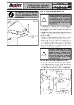
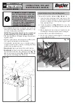
• Setting the travel (Fig. 19)
Tyre changers equipped with collapsible stand and
telescopic arm, tire changers, have both horizontal
and vertical adjusting clamps for horizontal and ver-
tical distance of the head from the rim, respectively.
Depressurize the air-operated cylinder (remove up-
per guard and
tighten the nut A1 first so to keep
the adjusting clamp horizontally, that is it should
be perpendicular to the hex. shaft
) and then turn
the nut
A
to adjust:
• turn the nut
A
clockwise for shorter travel of the
head;
• turn the nut
A
anti-clockwise for
longer travel of
the head.
Adjust the vertical clamp by turning nut
B
, with the
pneumatic cylinder depressurized (after the upper
guard has been removed and
after nut B1 has been
tightened), in order to lock the cone in fixed posi-
tion compared to the roller – see Fig. 19).
• turn the nut
B
clockwise for shorter travel of the
head;
• turn the nut
B
anti-clockwise for longer travel of
the head.
B1
B
1 mm
A1
A
Fig. 19
7300-M023-0_B
HP441S.XX - HP441S.XXFI
HP441SQ.XX - HP441SQ.XXFI


