INSTRUCTION, USE AND
MAINTENANCE MANUAL
Page 13 of 36
GB
10.7 Air connection
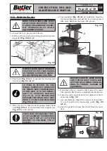
Connect the tyre changer to the workshop compressed
air system by means of plug (
Fig. 10 ref. 1
).
Fig. 10
The pressurized pipe coming from the mains must
have a section of 1/4x10 (
Fig. 10 ref. 2
).
The filter unit is already mounted on the machine.
10.8 Controls
BEFORE STARTING UP THE TYRE-
CHANGER, BE SURE TO BECOME
FAMILIAR WITH THE LOCATION
AND OPERATION OF ALL CON-
TROLS AND CHECK THEIR PROP-
ER OPERATION (SEE PAR. “CON-
TROLS”).
CARRY OUT A DAILY CHECK OF
MAINTAINED-TYPE CONTROLS
CORRECT FUNCTIONING, BEFORE
STARTING MACHINE OPERATION.
7300-M023-0_B
HP441S.XX - HP441S.XXFI
HP441SQ.XX - HP441SQ.XXFI
On delivery, the machines are preset to operate at
a three-phase voltage of 230/400V - 50-60 Hz (for
HP441S versions) or with a three-phase voltage of
230/400V - 50 Hz (for HP441SQ versions).
For any other type of power supply, ask the manufac-
turer at the time of purchase: a machine functioning
under the required voltage conditions will be prepared.
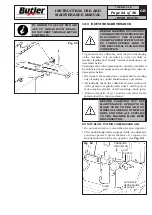
FIT A TYPE-APPROVED PLUG
TO THE MACHINE CABLE (THE
GROUND WIRE IS YELLOW/GREEN
AND MUST NEVER BE CONNECTED
TO ONE OF THE PHASE LEADS).
MAKE SURE THAT THE ELECTRI-
CAL SYSTEM IS COMPATIBLE
WITH THE RATED POWER AB-
SORPTION SPECIFIED IN THIS
MANUAL AND APT TO ENSURE
THAT VOLTAGE DROP UNDER
FULL LOAD WILL NOT EXCEED
4% OF RATED VOLTAGE (10%
UPON START-UP).
10.6 Check of motor rotation direction
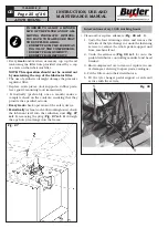
Once all power connections have been made, make
sure that the mandrel is rotating in the right direction
(pedal lowered, clockwise rotation). If the direction of
rotation is wrong, swap two phase wires in the plug.
FAILURE TO OBSERVE THE ABOVE
INSTRUCTIONS WILL IMMEDIATE-
LY INVALIDATE THE WARRANTY.


