background image

27

Electrical installation

9.4. 

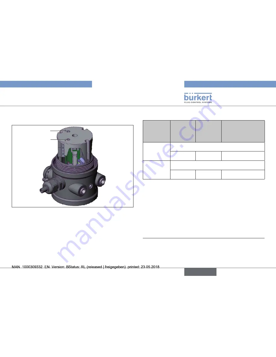
Display elements: End position 

LEDs

LED Top

LED Bottom

Fig. 25:  End position LEDs

9.4.1.  Display elements LEDs

Version 

with 3-wire 

proximity 

switches

Version 

with 2-wire 

proximity 

switches

Version with 2-wire 

proximity switches 

by NAMUR (Ex 

version)

6)

End 

position top

LED Top

is lit yellow

is lit yellow

goes out

End 

position 

bottom

LED Bottom

is lit yellow

is lit yellow

goes out

Tab. 7:  End position LED yellow

The version with micro switches (mechanical limit switches) does 

not include any LED to indicate position.

6) 

 In the case of the version with 2-

wire

 initiators according to NAMUR 

the LED function is inverse for technical reasons, i.e. the LED glows 

when the end position is not reached and goes out when the end 

position is reached.

english

Type 8697

Summary of Contents for 8697

Page 1: ...Operating Instructions Bedienungsanleitung Manuel d utilisation Type 8697 Pneumatic Control Unit Pneumatische Ansteuerung Unité de commande pneumatique ...

Page 2: ... right to make technical changes without notice Technische Änderungen vorbehalten Sous réserve de modifications techniques Bürkert Werke GmbH Co KG 2011 2018 Operating Instructions 1805 05_EU ml_00810081 Original DE ...

Page 3: ... Installation on process valves of series 20xx 15 7 4 Rotating the actuator module 18 7 5 Rotating the Pneumatic Control Unit for process valves belonging to series 20xx 19 7 6 Manual actuation of the actuator via pilot valve 20 8 FLUID INSTALLATION 21 8 1 Safety instructions 21 8 2 Installing the process valve 21 8 3 Pneumatic connection of the Pneumatic Control Unit 21 9 ELECTRICAL INSTALLATION ...

Page 4: ...rol Unit Type 8697 The abbreviation Ex used in these instructions always stands for explosion protected 1 OPERATING INSTRUCTIONS The operating instructions describes the entire life cycle of the device Keep these instructions in a location which is easily acces sible to every user and make these instructions available to every new owner of the device The operating instructions contain important sa...

Page 5: ... planned Correct transportation correct storage and installation and careful use and maintenance are essential for reliable and faultless operation Use the Pneumatic Control Unit Type 8697 only as intended 2 1 Designs with explosion protection DANGER Explosion hazard Improper use in a potentially explosive atmosphere represents an explosion hazard Observe the information in the EC Declaration of C...

Page 6: ...pair work may be carried out by authorized technicians only and with the appropriate tools After an interruption in the power supply or pneumatic supply ensure that the process is restarted in a defined or controlled manner The device may be operated only when in perfect condition and in consideration of the operating instructions The general rules of technology apply to application planning and o...

Page 7: ...com 5 DESCRIPTION OF SYSTEM 5 1 Configuration and function The Pneumatic Control Unit Type 8697 can control single or double acting process valves The Pneumatic Control Unit Type 8697 has been optimized for integrated modular installation on process valves of the 21xx series Element actuator size 50 The module configuration permits a variety of expansion steps For installation on the 20xx series t...

Page 8: ...itch cams only for model with inductive proximity switches Opening for optical position indicator Fig 2 Configuration and function 2 5 1 2 Model for control of process valves belonging to the 20xx series A special model enables the Pneumatic Control Unit Type 8697 to be attached to process valves belonging to the 20xx series This model has a different pneumatic connection module so that the pilot ...

Page 9: ...rea Observe the ATEX additional instructions The product is cULus approved Instructions for use in the UL area see chapter 6 9 Electrical data 6 4 Operating conditions WARNING Solar radiation and temperature fluctuations may cause malfunctions or leaks If the device is used outdoors do not expose it unprotected to the weather conditions Ensure that the permitted ambient temperature does not exceed...

Page 10: ...l 6 7 UL additional label Limit switch 10 30 V Type 4X enclosure Degree of protection Supply voltage limit switch Fig 5 Example of UL additional label example 6 8 Pneumatic data Control medium neutral gases air Quality classes in accordance with DIN ISO 8573 1 Dust content Class 7 max particle size 40 μm max particle density 10 mg m3 Water content Class 3 max pressure dew point 20 C or min 10 C be...

Page 11: ...tor load 2 A AC 0 4 A DC 2 A AC 0 2 A DC inductive load cos ϕ 0 3 0 5 A AC 0 2 A DC 0 2 A AC 0 1 A DC 1 When used in the UL area voltage and current are limited to 125 V AC 1A Also both micro switches must be fed from the same power supply Proximity switches 3 wire PNP 10 30 V DC max 100 mA per proximity switch 2 wire 24 V DC normally open 10 30 V DC max 100 mA min 3 mA per proximity switch Voltag...

Page 12: ... may be carried out by authorized technicians only and with the appropriate tools Risk of injury from unintentional activation of the system and an uncontrolled restart Secure system from unintentional activation Following installation ensure a controlled restart 7 2 Installation on process valves of series 21xx Procedure 1 Install switch spindle Transparent cap Actuator Pilot air ports plug in ho...

Page 13: ...nate the groove ring Do not apply any screw locking paint to the switch spindle To secure the switch spindle apply some screw locking paint Loctite 290 in the tapped bore of the spindle extension in the actuator Check that the O ring is correctly positioned Screw the guide element to the actuator cover maximum torque 5 Nm Screw switch spindle onto the spindle extension To do this there is a slot o...

Page 14: ...r ports Fastening screws max 0 5 Nm Fig 9 Installation of the Pneumatic Control Unit 21xx series Align the Pneumatic Control Unit until the supports of the Pneu matic Control Unit can be inserted into the pilot air ports of the actuator see also Fig 9 Push the Pneumatic Control Unit without turning it onto the actuator until no gap is visible on the form seal NOTE Too high torque when screwing in ...

Page 15: ...o not tighten spindle yet Guide element O ring Plastic part of the switch spindle Switch cam Switch spindle Spindle actuator Actuator cover Groove ring 3 Spacer sleeve Maximum distance Fig 11 Installation of the switch spindle 2 series 20xx Tighten the guide element with a wrench SW19 into the actuator cover torque 8 0 Nm Tighten the switch spindle on the spindle of the actuator To do this there i...

Page 16: ...2 If they are positioned differently longer hoses may be required other than those supplied in the accessory kit NOTE Too high torque when screwing in the fastening screw does not ensure degree of protection IP65 IP67 The fastening screws may be tightened to a maximum torque of 0 5 Nm only Attach the Pneumatic Control Unit to the actuator using the two side fastening screws In doing so tighten the...

Page 17: ...the ambient air is humid a hose can be connected between pilot air outlet 22 of the Pneumatic Control Unit and the unconnected pilot air port of the actuator for control function A or control function B As a result the spring chamber of the actuator is supplied with dry air from the vent duct of the Pneumatic Control Unit Control function Pneumatic connection Type 8697 with actuator Pilot air outl...

Page 18: ...14 Rotating the actuator module DANGER Risk of injury from high pressure in the equipment device Before working on equipment or device switch off the pressure and deaerate drain lines Procedure Clamp valve body in a holding device only required if the process valve has not yet been installed Control function A Open process valve Using a suitable open end wrench counter the wrench flat on the pipe ...

Page 19: ...sen the fastening screws hexagon socket wrench size 2 5 Rotate the Pneumatic Control Unit into the required position Pneumatic connection Fastening screw 2x Actuator Pneumatic Control Unit Fig 16 Rotating the Pneumatic Control Unit series 20xx NOTE Too high torque when screwing in the fastening screw does not ensure degree of protection IP65 IP67 The fastening screw may be tightened to a maximum t...

Page 20: ... pressed and turned Do not press the hand lever when turning it Pilot valve non activated normal position Hand lever Hand lever to the left Pilot valve activated Hand lever to the right Fig 17 Pilot valve for aerate and deaerate the actuator Move actuator to end position Turn the hand lever to the right using a screwdriver Note Do not press the hand lever when turning it Move actuator back to the ...

Page 21: ...olled restart 8 2 Installing the process valve Thread type and dimensions can be found in the corresponding data sheet Connect the valve according to the operating instructions for the valve 8 3 Pneumatic connection of the Pneumatic Control Unit DANGER Risk of injury from high pressure in the equipment device Before working on equipment or device switch off the pressure and deaerate drain lines Pr...

Page 22: ...ntrol Unit Cable bushing with cable gland M16 x 1 5 and screw type terminals Multi pole with circular plug in connector M12 x 1 8 pole 9 1 Safety instructions DANGER Risk of electric shock Before reaching into the device switch off the power supply and secure to prevent reactivation Observe applicable accident prevention and safety regulations for electrical equipment WARNING Risk of injury from i...

Page 23: ...nticlockwise direction Push the cables through the cable gland Connect the wires according to the model options of the Pneumatic Control Unit NOTE Damage or malfunction due to penetration of dirt and humidity To ensure degree of protection IP65 IP67 Tighten the union nut on the cable gland according to the cable size or dummy plugs used ca 1 5 Nm Screw the transparent cap in all the way Tighten un...

Page 24: ... Fig 20 Position of the screw terminals 9 2 2 Connection diagram with 3 wire proximity switches inductive limit switches Terminal Configuration External circuit 1 INI 24 V DC Supply 4 3 2 1 Output 2 24 V Output 1 24 V GND 24 V DC 2 INI GND Supply 3 INI Top OUT Output 1 4 INI Bottom OUT Output 2 5 Valve control 0 24 V DC 5 6 0 24 V DC 10 Residual ripple 10 6 Valve control GND Tab 3 Connection diagr...

Page 25: ...tion diagram with 2 wire proximity switches 3 Recommended by NAMUR Observe the max values of the intrinsically safe circuits in the ATEX additional instructions 4 Signal from barrier see PTB 07 ATEX 2048 Screw terminals 1 2 3 Terminal No 4 5 6 Fig 22 Position of the screw terminals 9 2 4 Connection diagram with 2 wire proximity switches 24 V inductive limit switches normally open Terminal Configur...

Page 26: ...ct the pins Pin assignment with 3 wire proximity switches inductive limit switches 1 2 5 6 4 7 3 8 Fig 24 Circular connector M12x1 8 pole Pin Wire color5 Configuration External circuit 1 white INI Bottom OUT Output 2 1 3 4 Output 2 24 V Output 1 24 V GND 24 V DC 2 brown INI Top OUT Output 3 green INI GND Supply 4 yellow INI 24 V DC Supply 5 grey Valve control 0 24 V 5 6 0 24 V DC 10 Residual rippl...

Page 27: ... top LED Top is lit yellow is lit yellow goes out End position bottom LED Bottom is lit yellow is lit yellow goes out Tab 7 End position LED yellow The version with micro switches mechanical limit switches does not include any LED to indicate position 6 In the case of the version with 2 wire initiators according to NAMUR the LED function is inverse for technical reasons i e the LED glows when the ...

Page 28: ... the end position is not reached and goes out when the end position is reached 9 5 Adjustment of the micro switches or the proximity switches option DANGER Risk of electric shock Before reaching into the device switch off the power supply and secure to prevent reactivation Observe applicable accident prevention and safety regulations for electrical equipment Procedure Open the Pneumatic Control Un...

Page 29: ...Screw the transparent cap in all the way Close the Pneumatic Control Unit assembly tool 6740787 Switch cam Fig 27 Adjustment of the micro switch and the proximity switches 8 The assembly tool 674078 is available from your Bürkert sales office 10 SAFETY POSITIONS Safety positions after failure of the electric or pneumatic auxiliary energy Operating mode Designation Safety positions after failure of...

Page 30: ...on of the system and an uncontrolled restart Secure system from unintentional activation Following disassembly ensure a controlled restart 12 2 Disassembly the Pneumatic Control Unit Procedure 1 Pneumatic connection DANGER Risk of injury from high pressure in the equipment device Before working on equipment or device switch off the pressure and deaerate drain lines Loosen the pneumatic connection ...

Page 31: ...E NOTE Transport damages Inadequately protected equipment may be damaged during transport During transportation protect the device against wet and dirt in shock resistant packaging Avoid exceeding or dropping below the permitted storage temperature Protect the electrical interfaces and the pneumatic connec tions from damage by placing protective caps on them Incorrect storage may damage the device...

Page 32: ......

Page 33: ...www burkert com ...

Reviews: