background image

43

SERVICE (CONT.)

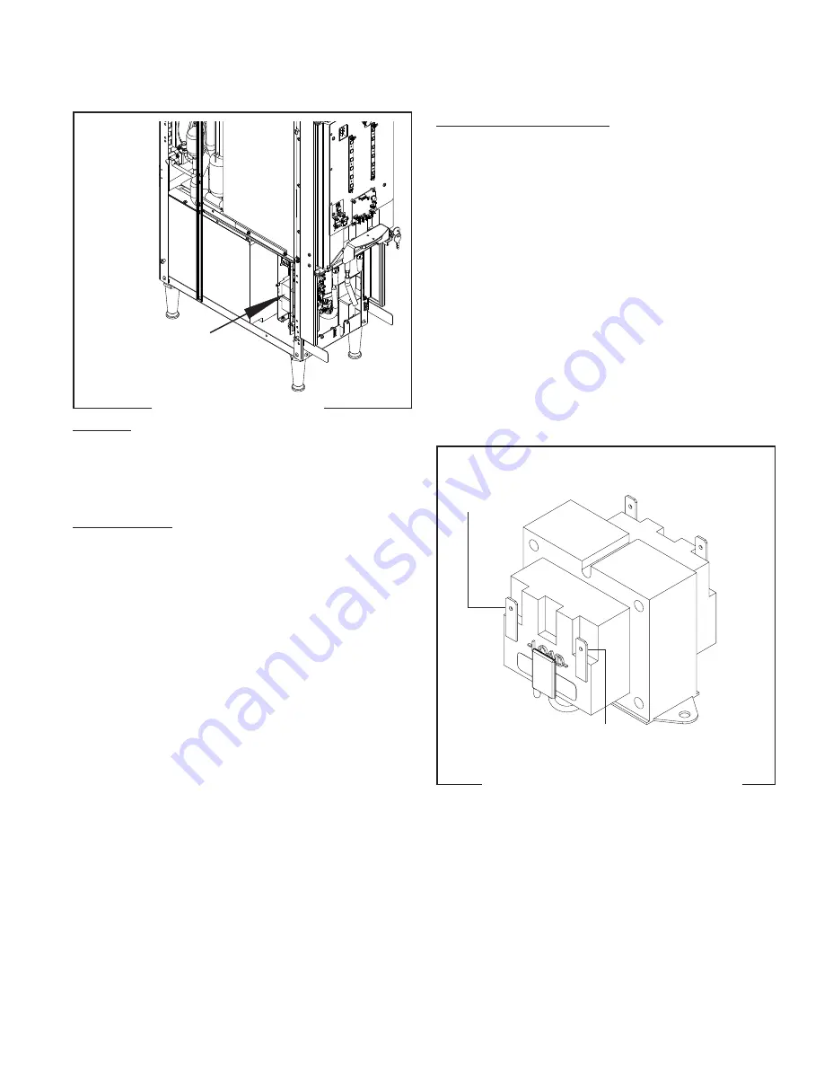
Transformer

Removal and Replacement:

1.  Loosen the two #8-32 screws securing the com-

ponent bracket to the dispenser housing base.

2.  Pull component bracket out the front of the dispenser 

far enough so the transformer can be disconnected 

from the main wiring harness.

3  Remove the two #6-32 keps nuts securing the 

transformer to the component bracket.

5.  Remove and discard the transformer.

6.  Install new transformer on the component bracket 

and secure with two #6-32 keps nuts.

7.  Refer to Fig. 52 and connect the transformer to the 

main wiring harness.

8.  Place the component bracket into position and 

tighten the two #8-32 screws.

BLU  to Control 

Board J6-3

WHI/BLU to Control 

Board J6-1

WHI from

Power Cord

BLK from

Power Cord

FIG. 52  TRANSFORMER TERMINALS

P1647

FIG. 51 TRANSFORMER

Location:

  The transformer is located on the electrical com-

ponent mounting bracket on the lower front of the 

dispenser behind the splash panel.

Test Procedure:

1.  Disconnect the dispenser from the power source.

2.  Check the voltage across black wire and the white 

wire from the main harness. Connect the dispenser 

to power source. The indication must be 120 volts 

ac.

4.  Disconnect the dispenser from the power source.

If voltage is present as described, proceed to #5.

If voltage is not present as described, refer to the Wiring 

Diagrams and check the main wiring harness.

5.  Check the voltage between J6-1 and J6-3 at the 

control board. Connect the dispenser to the power 

source. The indication must be 24 volts ac.

If voltage is present as described the transformer is 

operating properly.

If voltage is not present as described, replace the 

transformer.

55124  021418

Summary of Contents for Nitron Cold Draft

Page 1: ...revision of the Operating Manual or to view the Illustrated Parts Catalog Programming Manual or Service Manual please visit the Bunn O Matic website at www bunn com This is absolutely FREE and the qui...

Page 2: ...ments by such individuals whether oral or written do not constitute warranties and should not be relied upon If BUNN determines in its sole discretion that the equipment does not conform to the warran...

Page 3: ...required between the dispenser sides and the wall or another appliances For optimum performance do not allow warm air from surrounding machines blow on the JDF dispenser Leave some space so the dispe...

Page 4: ...finished productflowsfromthe dispense nozzles 13 Remove Air Filter from outside rear panel of dispenser 14 Wash Filter using warm soapy water rinse using water flow from faucet Shake out excess water...

Page 5: ...or damage and replace immediately Check and or replace every 6 months or as required 39690 0000 Pump Tube Replacement Kit Includes items indented below 28755 1011 Tube Norprene 25 ID x 17 0 lg 32732...

Page 6: ...avoid twists and kinks in the tubing Make certain that all plumbing connections are sealed and electrical connections tight and isolated WARNING Exercise extreme caution when servicing electrical equi...

Page 7: ...irty con denser filter or adequate ventilation and space around machine Checkrefrigerationsystemforleaks and proper charge Check Dispense switch is set to ON and sight gauge shows full water bath If s...

Page 8: ...alve failed A Set switch to ON position B Check switch and harness for proper continuity Check all previous items that pre tain to refrigeration or cold water recirculation Place switch in ON position...

Page 9: ...oper counterclockwise rotation of pump rollers If coun terclockwise replace pump tubing If clockwise wire connection to pump is reversed Switch wires on terminals A Check speed setting on circuit boar...

Page 10: ...n normal May fill drip tray during initial ice block formation Inspect or replace fittings clamps o rings solenoidsandquickdiscon nect fittings NOTE Dispensedeckareaslopesto draintubethatleadstothedri...

Page 11: ...ore use 35 40 Maintain 30 psi or higher and a minimum dynamic flow rate of 4 5 fl oz sec Over 100 psi install a pressure regulator and set to 50 psi A Perform3secondwaterdispense test Factory setting...

Page 12: ...eat it back down prop erly Follow step by step in structions on priming product through the system 1 Waituntilsystemisfullycooled and ice bank fully formed before setting preferred N2 pressure Check C...

Page 13: ...properly and if there s a shut off valve make sure shut off valve is open Check that water inlet pres sure has dynamic operating pressure between 30 to 90 psi If below 30 psi install water booster pu...

Page 14: ...up instructions before op erating the system 1 Wait until system is fully cooled and ice bank fully formed Check Compressor switch is set to ON and sight gauge shows full water bath If water bath sig...

Page 15: ...mea suring cylinder under the dis pense nozzle pull and release the tapper handle 3 times The dispenser will then dispense an amount of water for 3 sec onds If water flow rate is set too low adjust t...

Page 16: ...Fluctuations in water or gas supply pressures d Ambient temperature too high or low 2 System has internal malfunc tion and needs service by a technician 1 a Install a water line that is in accordance...

Page 17: ...oor panels dispenser top covers hopper s hopper support plate splash guard splash panel w drip tray lower front access panel and rear ac cess cover Refer to the contents listing for component location...

Page 18: ...ation Before removing panels make sure power is OFF to the machine and water is disconnected accept where indicated in testing procedures Retain all screws and other attaching hardware for re assembly...

Page 19: ...down 2 Lift and remove product shelf to access dispense platform 3 Remove front thumb screw holding dispense platform 4 Disconnect 12 pin connector above dispense platform in rear 5 Disconnect 3 8 wat...

Page 20: ...voltage is present as described replace the fan Ifvoltageisnotpresentasdescribed refertotheWiring Diagrams and check the dispenser wiring harness back to the transformer See TRANSFORMER Removal and Re...

Page 21: ...TERMINALS FIG 8 THERMAL OVERLOAD PROTECTOR TERMINALS Plugs into Relay Compressor Start Relay Refer to FIG 7 1 Disconnect the dispenser from the power source 2 Remove compressor terminal cover 1 3 Inst...

Page 22: ...replacing the compressor it is recom mended that the dryer also be replaced 1 Disconnect the tubes from the condenser and the accumulator 2 Disconnect the compressor wiring harness from the dispenser...

Page 23: ...ty is present as described reconnect the wires to the switch terminals If continuity is not present as described replace the switch Removal and Replacement 1 Disconnect the dispenser from the power so...

Page 24: ...bed replace the fan Removal and Replacement 1 Disconnect the dispenser from the power source 2 Remove the four screws attaching the fan and wire guard to the mounting bracket 3 Disconnect the 2 pin co...

Page 25: ...arness Connectthedispensertothepower source The indication must be 24 volts ac 6 Disconnect the dispenser from the power source Ifvoltageisnotpresentasdescribed refertotheWiring Diagrams and check the...

Page 26: ...t 1 Remove the five screws securing the door cover to the door frame 2 Carefully pull the cover forward and disconnect all switch harnesses from the connectors on the control board 3 Removethefour 6 2...

Page 27: ...p Meter should display around 36 amps 4 Visually ensure the pump is moving or circulating water Removal and Replacement 1 Remove dispense platform for ease of taking out recirculating pump 2 Remove le...

Page 28: ...heck for continuity between the terminals shown in Fig 21 Continuity must be present when the switch is in the ON position If continuity is not present replace the switch Removal and Replacement 1 Dis...

Page 29: ...rotor 3 Inspect the pump tubing for signs of wear and replace every six months or as needed 4 Inspectthepumprotorforsignsofwearandreplace if necessary 5 Install the new pump tube around the rotor and...

Page 30: ...t upon the dispense station pot dial setting 3 Disconnect the dispenser from the power source If voltage is present as described replace the motor Ifvoltageisnotpresentasdescribed refertotheWiring Dia...

Page 31: ...t 77 F temperature If readings are not as described replace the valve Removal and Replacement 1 Disconnect the two wires from the dispense valve 2 Remove the 6 32 screw and plate securing the water ma...

Page 32: ...ection If continuity is not present with the test magnet replace the reed switch If continuity is continuous without the test magnet replace the reed switch If continuity is present with the test magn...

Page 33: ...to Fig 32 and reconnect wires to the LED regulator board 7 Replace the door cover and secure with the five 6 32 screws 8 Return power to the dispenser FIG 32 LED DOOR LIGHT WIRING FIG 31 LED DOOR LIGH...

Page 34: ...D lamp 5 Install a new LED lamp 6 Reconnect wires to the LED harness 7 Replace the door cover and secure with the five 6 32 screws 8 Return power to the dispenser FIG 34 LED DOOR LIGHT WIRING FIG 33 L...

Page 35: ...chassis on the upper outside of the component bracket Test Procedures 1 Disconnect the dispenser from the power source 2 Disconnect the blue black wire and the red black wires from relay terminals 3 C...

Page 36: ...ts 4 Refer to Fig 38 to reconnect the wires Location The relay or contactor is located inside the dis penser chassis on the lower outside of the component bracket Test Procedures Continuity or Voltage...

Page 37: ...tinuity is present as described reconnect the wires to the switch terminals If continuity is not present as described replace the switch Removal and Replacement 1 Disconnect the dispenser from the pow...

Page 38: ...ce If the sound is heard as described and water will not pass through the solenoid valve there may be a block age in the water line before the solenoid valve or the solenoid valve may require inspecti...

Page 39: ...scribed reconnect the two wires to the solenoid If continuity is not present as described replace the solenoid valve Removal and Replacement 1 Disconnect the dispenser from the power source 2 Turn off...

Page 40: ...hen the On Off dispense switch is in the On position Test Procedures Float down position 0 00vdc or continuity across float contacts Float up position 5 0vdc or no continuity across float contacts Rem...

Page 41: ...erature probe while in the cup of ice water 32 F The resis tance should be within 31280 00 to 34022 00 Ohms 32 F If resistance is not to specification replace the tem perature probe Removal and Replac...

Page 42: ...ve the left side housing panel 2 Disconnect the plug on the temperature sensor leads from the connector on the dispenser main harness 3 Open the cabinet door and remove the product containers 4 Remove...

Page 43: ...om Power Cord FIG 52 TRANSFORMER TERMINALS P1647 FIG 51 TRANSFORMER Location The transformer is located on the electrical com ponent mounting bracket on the lower front of the dispenser behind the spl...

Page 44: ...ter water pump Removal and Replacement 1 Disconnect dispenser from the power source 2 Shut off nitrogen gas at supply tank 3 Remove the right side housing panel 4 Disconnect the plug on the booster pu...

Page 45: ...Unlock the adjustment knob and rotate knob while watching the pressure gauge for increase or decrease in water pressure If the water pressure or water flow doesn t change replace the regulator Remova...

Page 46: ...water to flow in reverse direction Removal and Replacement 1 Disconnect dispenser from the power source 2 Shut off water supply to the dispenser 3 Shut off nitrogen supply to the dispenser 4 Remove th...

Page 47: ...erminals when no N2 gas pressure is applied No continuity replace pressure switch Removal and Replacement 1 Disconnect dispenser from the power source 2 Shut off nitrogen supply to the dispenser 3 Rem...

Page 48: ...onnect fitting Connect the test gauge and turn N2 supply back on The pressure reading should be at 90psig Removal and Replacement 1 Disconnect dispenser from the power source 2 Shut off water supply t...

Page 49: ...the nozzle and gently remove insert Inspect the inner diameter of all five holes for product residue Clean and clear the residue from the holes Ensure all holes appear the same diameter size before in...

Page 50: ...0 Triac Map 1 2 3 4 5 6 7 8 9 10 11 1 Compressor Relay Q25 2 Not Used 3 Not Used 4 Not Used 5 Not Used 6 Not Used 7 Not Used 8 Not Used 9 Not Used Q11 10 Inlet Water Valve Q10 11 Not Used 55124 021418...

Page 51: ...T VALVE WATER BOOSTER PUMP WATER BOOSTER PUMP RELAY BRN WHI SOL BLK TRANSFORMER WHI BLU WHI BLU L O A D L I N E WHI WHI BLK K1 120V MODELS N A B A B A B L1 WHI GRN BRN WHI A B 220 230V MODELS GRN YEL...

Reviews: