background image

21

SERVICE (cont.)

HOPPER DELAY BOARD

FIG. 14 HOPPER DELAY BOARD

P1445.40

Location

The hopper delay board is located behind the

lower front access panel mounted in the center of the
component bracket.

Test Procedures:
1. Disconnect the dispenser from the power source.
2. Disconnect the eight pin plug on the main wiring

harness from the eight pin connector on the hop-
per delay board.

3. With the rinse/run switch in the “Run”, lower

position, check the voltage across the white and
black wires of the main wiring harness with a
voltmeter. Connect the dispenser to the power
source. The indication must be:
a) 120 volts ac for two wire 120 volt models.
b) 120 volts ac for three wire 120/208 volt or 120/
240 volt models.
c) 240 volts ac for two wire 240 volt models.

4. Disconnect the dispenser from the power source.

If voltage is present as described, proceed to #5.
If voltage is not present as described, refer to the wir-
ing diagram and check the dispenser wiring harness.

5.

Reconnect the eight pin connector of the hopper
delay board to the main harness.

6.

Check the voltage across the terminals  on the
auger motor with a voltmeter. Press and hold the
appropriate dispense switch. Connect the dis-
penser to the power source. After a delay of .7
seconds the indication must be:
a) 120 volts ac for two wire 120 volt models.

b) 120 volts ac for three wire 120/208 volt or 120/
240 volt models.
c) 240 volts ac for two wire 240 volt models.

7.

Disconnect the dispenser from the power source.

If voltage is present as described the hopper delay
board is operating properly.
If voltage is not present as described, replace the hop-
per delay board.

Removal and Replacement:
1.

Disconnect the eight pin plug from the hopper
delay board.

2.

Remove the two #8-32 keps nuts securing the
hopper delay board to the component bracket.

3.

Remove hopper delay board and discard.

4.

Install new delay board on the component bracket
using two #8-32 keps nuts.

5.

Reconnect the eight pin connector to the hopper
delay board.

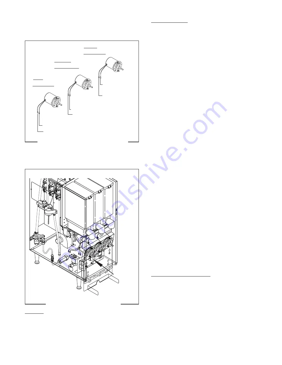
FIG.13 WHIPPER MOTOR TERMINALS

P1451.40

LEFT
FMD-2 & 3

CENTER
FMD-3 ONLY

RIGHT
FMD- 2 & 3

BLK to Main Harness RED
BLK to Main Harness WHI

BLK to Main Harness ORA
BLK to Main Harness WHI

BLK to Main
Harness WHI/VIO
BLK to Main
Harness WHI

FROTHER AND WHIPPER MOTOR (cont.)

28364 011598

Summary of Contents for FMD-2

Page 1: ...7 PHONE 217 529 6601 FAX 217 529 6644 www bunnomatic com FMD 2 FMD 3 prior to S N FMD0013000 HOT LIQ U ID RELEASE BUTTON WHEN CUP IS 2 3 FULL PLACE CUP HERE PLACE CUP HERE PLACE CUP HERE WARNING PUSH and HOLD BUTTON UNTIL CUP IS 2 3 FULL THEN RELEASE 28364 0000D 08 02 1998 Bunn O Matic Corporation BUNN ...

Page 2: ...r warranty THE FOREGOING WARRANTY IS EXCLUSIVE AND IS IN LIEU OF ANY OTHER WARRANTY WRITTEN OR ORAL EXPRESS OR IMPLIED INCLUDING BUT NOT LIMITED TO ANY IMPLIED WARRANTY OF EITHER MERCHANTABILITY OR FITNESS FOR A PARTICULAR PURPOSE The agents dealers or employees of BUNN are not authorized to make modifications to this warranty or to make additional warranties that are binding on BUNN Accordingly s...

Page 3: ...WHEN CUP IS 2 3 FULL PLACE CUP HERE PLACE CUP HERE FMD 2 28328 00003 FMD 3 28328 0000 HEATER 26527 0002 THERMOSTAT ASSEMBLY BUNN O MATIC CORP TEMPERATURE ADJUSTMENT 160 120VAC 190 MECHANICAL THERMOSTAT 28368 0000 ELECTRONIC THERMOSTAT 26536 0002 28364 071598 ...

Page 4: ...r source 5 If plumbing is to be hooked up later be sure the dispenser is disconnected from the power source If plumbing has been hooked up the dispenser is ready for Initial Fill Heat PLUMBING REQUIREMENTS This dispenser must be connected to a COLD WATER system with operating pressure between 20 and 90 psi 138 and 620 kPa from a 1 2 or larger supply line A shut off valve should be installed in the...

Page 5: ... the drip tray cover in place c Fill the hopper s with the dry product to be dispensed DISPENSER USE 1 Simply place a cup on the drip tray beneath the desired dispensing tip 2 Press the button to froth and dispense the beverage 3 Release the button when the cup is approximately 2 3 full and allow the mixing chamber to drain NOTE The mixing chamber must drain at the end of each dispense COLD BEVERA...

Page 6: ...ter exhausting the troubleshooting steps contact the Bunn O Matic Technical Service Department Inspection testing andrepairofelectricalequipmentshouldbeperformedonlybyqualifiedservicepersonnel All electronic components have 120 volt ac or 240 volt ac and low voltage dc potential on their terminals Shorting of terminals or the application of external voltages may result in board failure Intermitten...

Page 7: ... white wires and the black and white wires on three wire 120 240 volt dispenser A3 Check for 240 volts across the white and black wires on two wire 240 volt dispenser B Check circuit breakers or fuses Refer to Service Dispense Switch for testing procedure See page 17 Refer to Service Dispense solenoid valve for testing procedures See page 29 or 30 Refer to Service Solenoid Valve Inlet for testing ...

Page 8: ...regularly dependingonlocalwaterconditions Excessivemineralbuild uponstain lesssteelsurfacescaninitiatecorro sive reactions resulting in serious leaks 2 Control thermostat REMEDY A Direction of flow arrow must be pointing towards dispenser B Remove the strainer and check for obstructions Clear or replace Inspectthetankassemblyforexces sive lime deposits Delime as re quired Refer to Service Limit Th...

Page 9: ... Switch 1 Dispense switch 2 Dispense solenoid valve Hot or Cold REMEDY Inspectthetankassemblyforexces sive lime deposits Delime as re quired Removethedispensesolenoidvalve and clear any obstructions Rebuild orreplacethevalveifnecessary See page 29 or 30 RefertoService LevelControlBoard and Probe for testing procedures See page 24 Refer to Service Solenoid Valve Inlet for testing procedures See pag...

Page 10: ...rmostattemperaturesettings decal in USER NOTICES on page 3 B Reading for electronic thermo stat should be185 F to 190 F Adjust the control thermostat to in crease or decrease the water tem perature Replace if necessary RefertoService WhipperMotorfor testing procedure See page 19 Refer to Service Frother Compo nents See page 19 RefertoService DispenseSolenoid Valve for test procedures See page 29 o...

Page 11: ...the dispenser must not exceed 90 psi 620 kPa Install a regulator if necessary to lower the working pressure to ap proximately 50 psi 345 kPa Remove and clean lime off the tank heater See page 32 Refer to Service Fan for testing procedures See page 18 RefertoService HopperDelayBoard for testing procedures See page 21 RefertoService Lamp seepage23 for lamp replacement Refer to Service Lamp Holder fo...

Page 12: ...Level Control Board and Level Probe 24 Limit Thermostat 26 Overflow Protection Switch 27 Rinse Run Switch 28 Solenoid Cold Drink Optional 29 Solenoid Dispense 30 Solenoid Inlet 31 Tank Heater 32 Tank Heater Switch 33 Whipper Motor 19 Wiring Diagrams 35 36 FIG 1 AUGER DRIVE COMPONENTS Location The auger components are located inside the bottom part of the hopper except for the auger drive bracket w...

Page 13: ... and lifting agitator disc assy from hopper 10 6 Remove auger 12 by pulling it out the front of the hopper 10 7 Remove auger drive shaft 5 by removing the retaining clip 6 from auger drive shaft 8 Slide washer 8 and auger drive shaft bracket 7 off of the auger drive shaft 5 9 Slide auger drive shaft 5 from auger drive shaft bushing 3 and remove from hopper 10 10 Remove locknut 9 from auger drive s...

Page 14: ...ounting bracket 16 au ger motor 17 and dust seal 18 as an assembly 6 Remove dust seal 18 from auger motor 17 7 Remove the four 8 32 screws securing the auger motor to the auger motor mounting bracket 8 Remove auger motor and discard 9 Using four 8 32 screw install new auger motor 17 on mounting bracket 16 10 Install dust seal 18 on auger motor shaft 11 Using four 8 32 locking screws install auger ...

Page 15: ...e The indi cation must be a 120 volts ac for two wire 120 volt models b 120 volts ac for three wire 120 208 volt models or 120 240 volts models c 240 volts ac for two wire 240 volt models If voltage is present as described the ballast is oper ating properly If voltage is not present as described replace the ballast Removal and Replacement 1 Disconnect the wires from the ballast 2 Remove the one 8 ...

Page 16: ... the black wire from the control thermostat and the white or red wire on the tank heater with the tank heater switch in ON lower position with a voltmeter Connect the dispenser to the power source The indication must be a 120 volts ac for two wire 120 volt models b 120 volts ac for three wire 120 208 volt or 120 240 volt models c 240 volts ac for two wire 240 volt models If voltage is present as d...

Page 17: ... PUSH an d HOLD BUTTON UNTIL CUP IS 2 3 FULL THEN RELEASE NOTE The center dispense switch is for FMD 3 Mod els only Test Procedure 1 Disconnectthedispenserfromthepowersource 2 Open the dispenser door and remove the bottom door cover 3 Disconnect the wires from the door interconnect wiring harness to the dispense switch to be tested 4 Check for voltage across the black and red black wires for the r...

Page 18: ...re to the dispenser housing base plate using two 8 32 locking screws SERVICE cont 6 Check for continuity across the terminals on the dispense switch with the switch in the ON pressed position Continuity must not be present when the switch is in the OFF released posi tion If continuity is present as described reconnect the connector to the door interconnect wiring harness the switch is operating pr...

Page 19: ...R AND WHIPPER MOTOR FIG 11 FROTHER AND WHIPPER MOTOR P1450 40 Location The frothers are located behind the dispenser door mounted on the whipper motor shaft inside the whipper chamber The whipper motors are located on the back side of the whipper motor mounting panel NOTE The center position is for FMD 3 Models only Test Procedure 1 Disconnect the dispenser from the power source 2 Disconnect the w...

Page 20: ...2 acorn nuts 11 and con nect black leads on the motor to the main wiring harness Refer to FDig 13 when reconnecting wires 18 Slide o ring 10 onto the motor shaft to approxi mately 1 16 of the front panel 19 Wash remaining components in a mild solution of dish detergent using a bristle brush 20 Rinse thoroughly and allow to dry before reinstall ing in the dispenser 21 Place teflon washer into back ...

Page 21: ...the main harness 6 Check the voltage across the terminals on the auger motor with a voltmeter Press and hold the appropriate dispense switch Connect the dis penser to the power source After a delay of 7 seconds the indication must be a 120 volts ac for two wire 120 volt models b 120 volts ac for three wire 120 208 volt or 120 240 volt models c 240 volts ac for two wire 240 volt models 7 Disconnect...

Page 22: ...not present as described refer to the wiring diagram and check the main wiring harness 5 Disconnect the wires from the switch termi nals 6 With the switch in the upper Cold position check for continuity between the center terminal and the bottom terminal With the switch in the down Hot position check for continuity between the center terminal and the upper terminal If continuity is present as desc...

Page 23: ...nd remove from lamp hold ers 2 8 Removethe 6 32screwsecuringthelampholder 2 to be removed remove lamp holder 2 and discard 9 Install new lamp holder 2 and secure with a 6 32 screw 10 Connect the wires on the new lamp holder to the door wiring harness 11 Install lamp 3 into lamp holders 2 and turn 90 until the pins snap in place 12 Install upper door panel 4 lamp 3 lamp hold ers 2 and door wiring h...

Page 24: ...the starter socket If continuity is present as described the starter socket is operating properly Ifcontinuityisnotpresentasdescribedreplacethethe starter socket 6 Remove starter 6 from starter socket 7 Checkforcontinuityacrossthepinsonthebottom of the starter 6 If continuity is present as described replace the starter If continuity is not present as described starter is operating properly Note If...

Page 25: ... for corrosion Replace it if necessary 13 Place the probe so that neither end is in contact with any metal surface of the dispenser 14 Check the voltage across terminals 1 3 with a voltmeter Connect the dispenser to the power source Theindicationmustbe120voltsacfortwo wire 120 volt models three wire 120 208 volt models three wire 120 240 volt models and 240 volts ac for two wire 240 volt models af...

Page 26: ... present as described the limit thermo stat is operating properly If continuity is not present as described replace the limit thermostat FIG 21 LIMIT THERMOSTAT TERMINALS P1800 Removal and Replacement 1 Remove all wires from the limit thermostat ter minals 2 Carefully slide the limit thermostat out from un der the retaining clip and remove the limit ther mostat 3 Carefully slide the new limit ther...

Page 27: ...ue wire from the liquid level board If continuity is not present as described replace the overflow protection switch Removal and Replacement 1 Disconnect the red leads from the overflow pro tection switch from the black wire from the main harness and the blue wire from the liquid level board 2 Remove the nut beneath the copper overflow cup 3 Remove the entire switch assembly from the cup 4 Place t...

Page 28: ...is operating properly If continuity is not present as described replace the switch Removal and Replacement 1 Open the dispenser door 2 Remove the facenut securing the run rinse switch to the whipper motor mounting panel 3 Remove switch with wires attached from the back side of the whipper motor mounting panel 4 Disconnect the wires from the switch and dis card the switch 5 Refer to Fig 25 when con...

Page 29: ...ct the dispenser to the power source With HOT COLD switch in the COLD upper position press the left dispense switch and listen carefully in the vicinity of the solenoid valve for a clicking sound as the coil magnet attracts 7 Disconnect the dispenser from the power source If the sound is heard as described and water will not pass through the solenoid valve there may be a block age in the water lin...

Page 30: ...ss the solenoid valve coil terminals If continuity is present as described reconnect the white and white violet orange or tan wires to the so lenoid If continuity is not present as described replace the solenoid valve 6 Check the solenoid valve for coil action Connect the dispenser to the power source With RUN RINSE switch in the RINSE upper position press the appropriate dispense switch and liste...

Page 31: ...ct the white and violet wires from the solenoid valve 3 Check the voltage across the white and violet wires with a voltmeter Connect the dispenser to the power source The indication must be 120 volts ac for two wire 120 volt models three wire 120 208 120 240 volt models and 240 volts ac for two wire 240 volt models 4 Disconnectthedispenserfromthepowersource If voltage is present as described proce...

Page 32: ... lines to and from the solenoid valve 7 Refer to Fig 31 when reconnecting the wires P1217 FIG 31 INLET SOLENOID VALVE TERMINALS TANK HEATER FIG 32 TANK HEATER P1445 40 Location The tank heater is located inside the tank and secured to the tank lid Test Procedure 1 Disconnect the dispenser from the power source 2 Checkthevoltageacrosstheblackandwhitewires 120 volt or 240 volt models or black and re...

Page 33: ...n 8 32 nuts securing the tank lid to the tank 9 Remove tank lid with limit thermostat liquid level probe and tank heater as an assembly 10 Remove the two hex nuts securing the tank heater to the tank lid Remove tank heater with gaskets and discard 11 Install new tank heater with gaskets on the tank lid and secure with two hex nuts 12 Install tank lid with limit thermostat liquid level probe and ta...

Page 34: ...anual and remove the hopper assemblies and the hopper support plate 2 Remove the switch mounting nut on the front of the front panel 3 Remove switch with wires attached from the rear of the front panel 4 Remove the wires from the switch terminals and discard switch 5 Connect the wires to the new switch refer to fig 35 5 Push new switch through hole in the front panel and secure with face nut 7 Ref...

Page 35: ...K HEATER RED 16 3 WIRE MODELS WHI 16 2 WIRE MODELS BLK 16 SOL TANK INLET BLK WHI WHI BLU PROBE 1 4 3 2 LIQUID LEVEL BOARD VIO WHI PNK RED RED OVERFLOW SWITCH FAN HEATER SW THERMOSTAT BLK 16 1 2 3 4 5 6 7 8 BLK RED WHI VIO ORA WHI HOPPER DELAY BLK WHI WHI WHI BLK BLK WHI RED BLU STARTER BLK BLK BLU RED RED BLK BLK BLK RED BLK BLK RED RED BLK RED WHI BLU WHI BLK BLK BLK WHI DISPENSE SWITCH RIGHT MOD...

Page 36: ...0 HZ 28341 0001E 6 98 1997 BUNN O MATIC CORPORATION SCHEMATIC WIRING DIAGRAM FMDA 1 FMDA 2 FMDA 3 GRN L1 L2 LIMIT THERMOSTAT BLK 16 TANK HEATER WHI 16 BLK 16 SOL TANK INLET BLK WHI WHI BLU PROBE 1 4 3 2 LIQUID LEVEL BOARD VIO WHI PNK RED RED OVERFLOW SWITCH FAN HEATER SW THERMOSTAT BLK 16 1 2 3 4 5 6 7 8 BLK RED WHI VIO ORA WHI HOPPER DELAY BLK WHI WHI WHI BLK BLK WHI RED BLU STARTER BLK BLK BLU R...

Reviews: