background image

Page 4

For technical questions, please call 1-800-444-3353.

Item  61229        

Sa
FE

tY

O

PER
ati

O

n

nE
tWOR

k

SE

ttin

GS

DVR Safety Warnings

1.  Maintain adequate airflow around DVR.

2.  Use supplied Power Adapter only.

3. 

Do not expose the Power adapter or DVR 

console to rain or wet conditions. Water 

entering the Power Adapter or DVR console 

will increase the risk of electric shock.

4. 

Do not abuse the Power adapter cord.  never 

use the cord for unplugging the plug from the 

outlet.  keep cord away from heat, oil, sharp 

edges or moving parts.  Damaged or entangled 

cords increase the risk of electric shock.

5.  Maintain labels and nameplates on the unit.  

These carry important safety information.  If 

unreadable or missing, contact Harbor 

Freight Tools for a replacement.

6.  WARNING: Handling the cord on this product will 

expose you to lead, a chemical known to the State 

of California to cause cancer, and birth defects or 

other reproductive harm. Wash hands after handling.  

(California Health & Safety Code § 25249.5, 

et seq.

)

7.  The warnings, precautions, and instructions 

discussed in this instruction manual cannot 

cover all possible conditions and situations 

that may occur.  It must be understood by the 

operator that common sense and caution are 

factors which cannot be built into this product, 

but must be supplied by the operator.

 SaVE thESE inStRuCtiOnS. 

Grounding

tO PREVEnt ElECtRiC ShOCk anD DEath FROm 

inCORRECt GROunDinG WiRE COnnECtiOn: 

Check with a qualified electrician if you are in doubt as to whether the outlet is properly 

grounded.  Do not modify the power cord plug provided with the tool.  never remove the 

grounding prong from the plug.  Do not use the tool if the power cord or plug is damaged.  if damaged, have 

it repaired by a service facility before use.  if the plug will not fit the outlet, have a proper outlet installed by 

a qualified electrician.

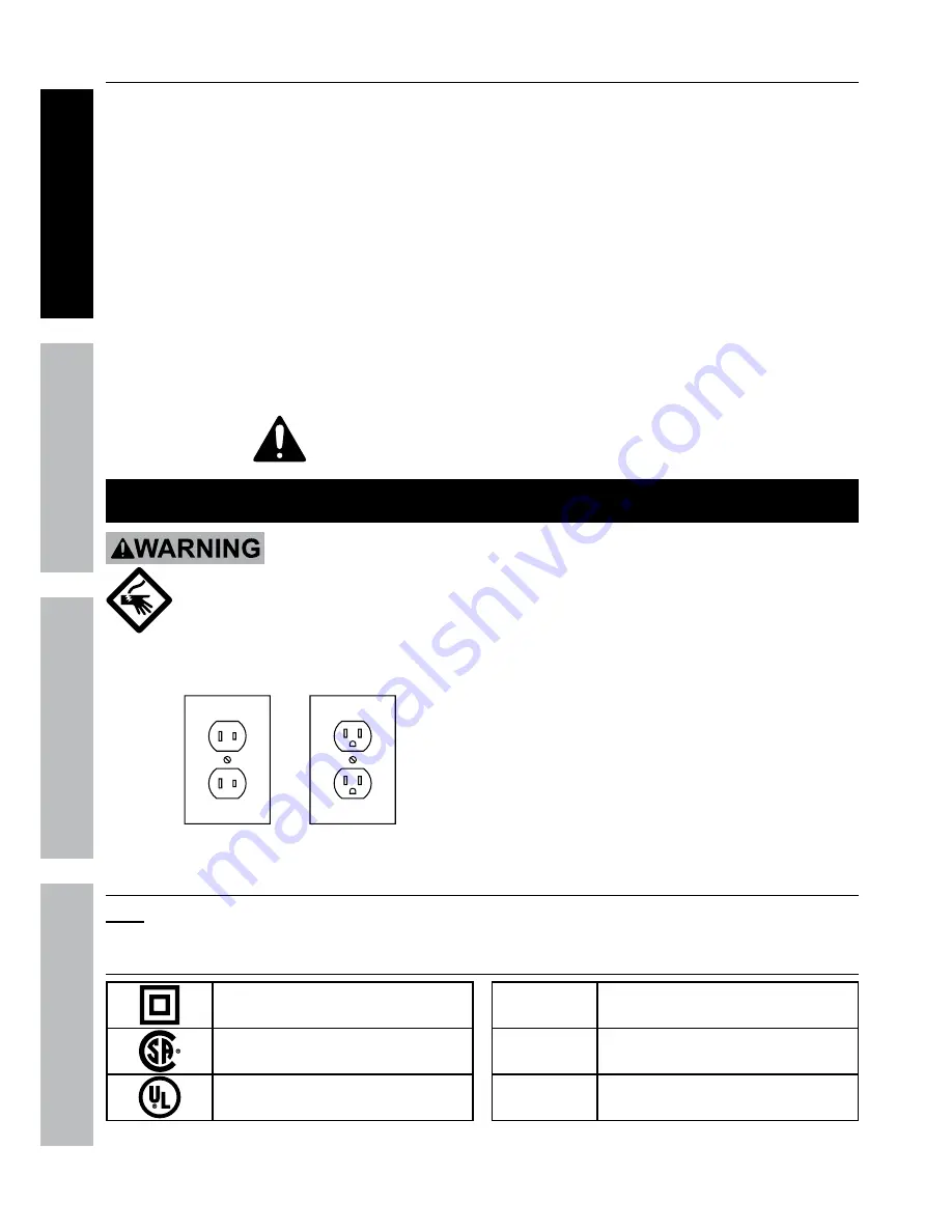
Figure a:  Outlets for 2-Prong Plug

1.  The included Power Adapters do 

not require grounding.

2.  The Power Adapters may be used in 

either of the 120 volt outlets shown in the 

preceding illustration.  

(See Figure a.)

Extension Cords

note:

  Do not use an extension cord with the Power Adapters.

Symbology

Double Insulated

Canadian Standards Association

Underwriters Laboratories, Inc.

V

Volts

~

Alternating Current

a

Amperes

Summary of Contents for 61229

Page 1: ... for future reference When unpacking make sure that the product is intact and undamaged If any parts are missing or broken please call 1 800 444 3353 as soon as possible Copyright 2013 by Harbor Freight Tools All rights reserved No portion of this manual or any artwork contained herein may be reproduced in any shape or form without the express written consent of Harbor Freight Tools Diagrams withi...

Page 2: ...e 31 DVR Client 31 Video Player 32 MAC Record Player 32 AVI Generator 32 Smartphone 32 Maintenance Instructions 33 Troubleshooting 34 Parts List 35 Warranty 36 WARNING SYMBOLS AND DEFINITIONS This is the safety alert symbol It is used to alert you to potential personal injury hazards Obey all safety messages that follow this symbol to avoid possible injury or death Indicates a hazardous situation ...

Page 3: ...wer Adapter plugs must match the outlet Never modify the plug in any way Unmodified plugs and matching outlets will reduce risk of electric shock 2 Do not expose DVR unit to rain or wet conditions Water entering the DVR will increase the risk of electric shock 3 Do not abuse the cord Never use the cord for carrying pulling or unplugging the power tool Keep cord away from heat oil sharp edges or mo...

Page 4: ...nd instructions discussed in this instruction manual cannot cover all possible conditions and situations that may occur It must be understood by the operator that common sense and caution are factors which cannot be built into this product but must be supplied by the operator Save these instructions Grounding To prevent electric shock and death from incorrect grounding wire connection Check with a...

Page 5: ...Detection PTZ Interface RS485 Supports Pelco D P camera sold separately Network Interface RJ 45 10m 100m Ethernet Interface USB Interface USB 2 0 DVR Input Rating 12VDC 2A Operating Temperature 32º 131ºF Cameras Lens Types 2 Cameras with fixed 6 mm lenses 2 Cameras with fixed 3 6 mm lenses Horizontal Resolution 400 TVL Effective Pixels 648H x 488V Night Vision Type Infrared LEDs with Low Light Sen...

Page 6: ...3 Red Hard Disk Drive Activity Indicator 4 Search Recordings 5 Mute 6 Previous Channel 7 Next Channel 8 Toggle 4 and 9 Screen Displays 9 Menu Up PTZ Up 10 PTZ Control Mode 11 Rewind Activate Controls 12 Pause 13 Play 14 Fast Forward 15 Stop 16 Start Manual Recording 17 Open Menu Escape PTZ Left 18 Menu Down PTZ Down 19 Confirm Selection Edit Selected Setting PTZ Right Note Controls for PTZ mode ar...

Page 7: ...4 and 9 Screen Displays MENU Open Menu MUTE Mute SUBMENU Open Pop Up Menu Menu Up Menu Down Menu Left Menu Right SEL Confirm Selected Operation Rewind Play Search Records Fast Forward Record ll Pause Stop Figure D Camera and Accessories Video from Camera Video to DVR Power to Camera Power from Splitter Cable 60 ft Screws Anchors Mounting Hardware Power from Cable Video to Cable Camera Hood Lens Po...

Page 8: ...following flow charts to help make the cable connections navigate the system and set up or change the unit settings Refer to the individual setup sections in this manual for detailed instructions on specific tasks INITIAL SETUP Physical Connections 1 B1 B2 B3 B4 D2 D3 D4 B5 B1 B2 B1 B2 B1 B2 D5 D1 USB Port Video Input A B C B C D A Connect Monitor Connect Cameras Connect Mouse Power Input Video Ou...

Page 9: ...n Menu select Record Press REC on front of DVR red light will flash Select Schedule Select Channel and Day of Week Select boxes for Normal and Motion 3 Repeat for all Days and all Channels Click Apply then OK In DVR Main Menu Select Alarm Select Motion Select Channel Set Sensitivity Level Select Area Select which Channels will record Click Apply then OK Set Buzzer for audible alarm Set Date and Ti...

Page 10: ...ts to a number between 200 and 255 Change last 3 digits to a number between 100 and 255 Click Apply then OK to save changes Click Exit DVR will prompt restart Click OK After restart on DVR go to Network Network to view settings Open Internet Explorer In address bar type in DVR s IP Address and HTTP Port http xxx xxx xxx xxx 3001 where x IP Address and 3001 HTTP Port Press Enter Allow ActiveX Contr...

Page 11: ...ess Enter Find the Router s IP Address by going to whatsmyip com Write it down On remote computer Open Internet Explorer In address bar type in Router s IP Address and HTTP Port from LAN Setup above http xx xxx xxx xxx 3001 where x IP Address and 3001 HTTP Port Press Enter Allow ActiveX Control to install You may need to adjust the settings in Internet Explorer by adding the http address to Truste...

Page 12: ...tate and local surveillance laws before installing video and or audio surveillance equipment Connect and test all equipment and camera locations before installing cameras Use a surge protector sold separately to protect equipment INITIAL SETUP Physical Connections 1 B1 B2 B3 B4 D2 D3 D4 B5 B1 B2 B1 B2 B1 B2 D5 D1 USB Port Video Input A B C B C D A Connect Monitor Connect Cameras Connect Mouse Powe...

Page 13: ...nnect Power Red from Cameras to Cables 3 Connect Video Yellow from Cables to DVR 4 Connect Power from Cables to Splitter 5 Connect Splitter to Camera Adapter C Connect Mouse Plug the Mouse in one of the USB ports D Connect Power Note Only use supplied Power Adapters and a surge protector sold separately 1 Plug Monitor into surge protector 2 Plug DVR Adapter into Power Input on DVR 3 Plug DVR Adapt...

Page 14: ...re F Solid Surface 1 Using a drill bit slightly smaller than the Screws drill pilot holes into the marked locations 2 Position Camera so that mounting holes align with pilot holes Note Route Cable through slot on Base to keep Base flush with mounting surface 3 Drive Screws through mounting holes in Base and into pilot holes until the Camera is securely attached to the mounting surface Hollow Surfa...

Page 15: ...screen Main Menu 4 way Split Screen Start PTZ Cruise PTZ 9 way Split Screen Record Search Zoom Record Stop Record Start SEQ PIP x1 PIP x2 Volume Figure H Main Menu Shortcut To Main Menu 4 way Split Screen Display Up To 4 Live Images 9 way Split Screen Display Up To 8 Live Images PTZ Go To PTZ Controls Start Cruise Start programmed PTZ Cruise Zoom Zoom PTZ Camera Record Search Go To Record Search R...

Page 16: ...one p 22 Output p 22 Live p 21 Record MainStream p 23 Schedule p 18 Rec Para p 23 Search Log p 26 Backup p 26 Event Search p 26 Record Search p 26 Network DDNS p 30 SubStream p 29 Network p 28 Email p 29 Mobile p 29 Device HDD p 27 PTZ p 27 System General p 17 Users p 20 Version p 21 Advanced Maintain p 24 Events p 24 Alarm Motion p 19 Figure J ...

Page 17: ...l not be saved unless you click Apply then OK Click Exit to return to System and discard unsaved changes 7 NTP Network Time Protocol Setup Click to open set up window Note This feature sets the internal clock from an Internet server The DVR must be connected to the Internet for this feature to work See Local Area Network LAN Setup on page 28 Figure M a Server Address Select server b Time Zone Sele...

Page 18: ...ormal continuous recording This is the Default setting Bottom row When selected boxes will turn yellow to indicate recording will be triggered by Motion Detection c Copy Date Copy parameters from one Day to other Days d Select Day to copy from e Select Day to copy to or select ALL f Click Copy then click OK 4 Copy Channel Copy parameters from one Channel to other Channels a Select Channel to copy ...

Page 19: ...mail sent when Motion Detection is triggered Note The DVR must be connected to the Internet for this function to work See Wide Area Network WAN Setup on page 30 8 Full Screen Check box so that when Motion Detection is triggered the Camera s view will display in full screen mode 9 Record Channel Check box to Enable Disable motion recording Highlight Channels to link recording to this Channel s moti...

Page 20: ...ord must be 6 numbers b Confirm Enter Password again to confirm Changes will not be saved unless you click Apply then OK Click Exit to return to System and discard unsaved changes 8 Select User that was just named and click Permission a Click in boxes to select specific permissions b Click All to select all permissions c Click Clear to remove all permissions Figure Q Log Search Check entire system...

Page 21: ... Channel 2 Name Set Channel name up to 8 characters 3 Position Select position where Channel Name will appear on the screen a U L Upper Left b D L Lower Left c U R Upper Right d D R Lower Right e Close No name will appear 4 Color Click Setup to adjust Hue Brightness Contrast and Saturation Changes will not be saved unless you click Apply then OK Click Exit to return to System and discard unsaved c...

Page 22: ...ill not be saved unless you click Apply then OK Click Exit to return to System and discard unsaved changes Privacy Zones Display Privacy Zone Allows selection of up to four areas to be blocked from being viewed or recorded Figure W 1 Channel Select Channel 2 Privacy Zone Toggles Privacy Zones 3 Area Setup Select up to 4 areas to block 4 Mask Area Select Setup then click and drag green square s to ...

Page 23: ...nless you click Apply then OK Click Exit to return to System and discard unsaved changes Video Stream Record MainStream Set Resolution Frames Per Second Bitrate Audio Figure Y Resolution Quality Fps Range Bitrate Range CIF 352X240 Low 1 30 224 768 HDI 704x240 Better 1 15 80 448 D1 704x480 Best 1 7 80 448 Figure Z 1 Resolution Select CIF D1 or HD1 2 Fps Frames per second Set as desired 3 Bitrate Kb...

Page 24: ...m default settings 5 Reboot Click to manually reboot system 6 Shut Down Click to manually shut down system Changes will not be saved unless you click Apply then OK Click Exit to return to System and discard unsaved changes Alerts Advanced Events Set up alerts for when the hard drive has no disk space when there is a disk error or a camera loses video Figure AB 1 Event Type Select Event type 2 Enab...

Page 25: ...hannel s to view then click Play 3 The Playback Control Bar will pop up on bottom of screen Note The Playback Control Bar will automatically disappear when the mouse stops moving To recall Playback Control Bar move the mouse Figure AE Rewind 2X 4X 8X 16X Play 1 2 1 4 1 8 speed Play normal speed Pause Fast Forward 2X 4X 8X 16X MUTE Turn off sound if audio hooked up Volume Control Control volume if ...

Page 26: ...4 TYPE Select All Normal or Alarm recordings a Normal recordings are scheduled or manual recordings b Alarm recordings are recordings started automatically by motion detection 5 Click Search to populate table 6 Select recordings to backup a To mark all recordings for backup click ALL b To mark recordings for backup click on BAK box for each selection c Click Backup and click OK to backup selected ...

Page 27: ...elect how long to save recordings on Hard Disk Drive before overwriting Note The drive will save recordings as long as possible before overwriting while in Auto mode If Close is selected the drive will not be overwritten 2 Format Hard Drive a Click Select box for drive to format b Click Format HDD c Click OK d When formatting is finished click OK 3 Format USB Drive a Install drive into USB port b ...

Page 28: ...efault Gateway are 0 99 change last 3 digits to a number between 100 and 255 b If last 3 digits of Default Gateway are 100 or more change last 3 digits to a number between 200 and 255 c New DVR IP Address will be xxx xxx xxx yyy where x first 3 sets of current Default Gateway Router s IP Address and y new set created in 3 a or b d Write the New DVR IP Address in the chart above 4 On DVR go to Netw...

Page 29: ...der Email The email address that the notification will be sent from 2 Sender Pwd The password for the email account that the notification will be sent from 3 Receiver Email The email address that the notification will be sent to Changes will not be saved unless you click Apply then OK Click Exit to return to System and discard unsaved changes Set up Smartphone Capability Network Mobile Figure AR 1...

Page 30: ...orwarding b If DHCP the IP Address will change at some point in time When it changes you will then need to use the new IP Address to connect to the DVR Other options are Contact your ISP and request a Static IP Address for which there may be a charge Set up a Dynamic Domain Naming System This is outside the scope of this manual Settings can be accessed on the Network DDNS tab 4 Go to Port Forwardi...

Page 31: ... User Name and Password 3 Video surveillance client will open Figure AS Add DVR 1 Click Config to open Local parameter configuration window 2 Click on Device manage 3 Right click on Device List then click Add Device This will open Manually add the device window Client Port Area Name Figure AT a Device Assign name to DVR b Device IP LAN computer use DVR s LAN Address from chart on page 28 Remote co...

Page 32: ...onverting recordings from H 264 to AVI format Insert supplied CD into computer open AVIGenerator and follow instructions Smartphone For connecting to the DVR from a smartphone To use this feature the WAN needs to be set up first 1 Insert supplied CD into computer and open Mobile Software folder for instructions according to phone type Note The phone s Unknown Sources setting MUST be enabled to all...

Page 33: ...lug the Power Adapter from its electrical outlet before inspection maintenance or cleaning 1 Periodically inspect the general condition of the Camera Check for loose hardware damaged cord electrical wiring cracked or broken parts and any other condition that may affect its safe operation 2 Periodically wipe external surfaces of Camera with clean cloth 3 Maintain area surrounding Camera making sure...

Page 34: ...1 Check that all connections are secure and in the correct location 2 Adjust the image settings on the monitor Poor quality images Setting s are incorrect Adjust settings for Video Stream on page 23 Error codes when trying to install DvrClient software Incompatibility with Operating System Check System Requirements on page Video Client DvrClient on page 32 to make sure your Operating System is sup...

Page 35: ... Cable 1 4 Remote Control 1 Part Description Qty 5 Mouse 1 6 Power Splitter 1 7 Camera Mounting Hardware 1 8 3 6 mm Lens Camera 2 9 6 0 mm Lens Camera 2 10 Cable 60 ft 4 Record Serial Number Here Note If product has no serial number record month and year of purchase instead Note Some parts are listed and shown for illustration purposes only and are not available individually as replacement parts ...

Page 36: ...damages so the above limitation of exclusion may not apply to you This warranty is expressly in lieu of all other warranties express or implied including the warranties of merchantability and fitness To take advantage of this warranty the product or part must be returned to us with transportation charges prepaid Proof of purchase date and an explanation of the complaint must accompany the merchand...

Reviews: