Name of Part
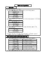
Display Part
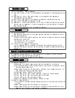
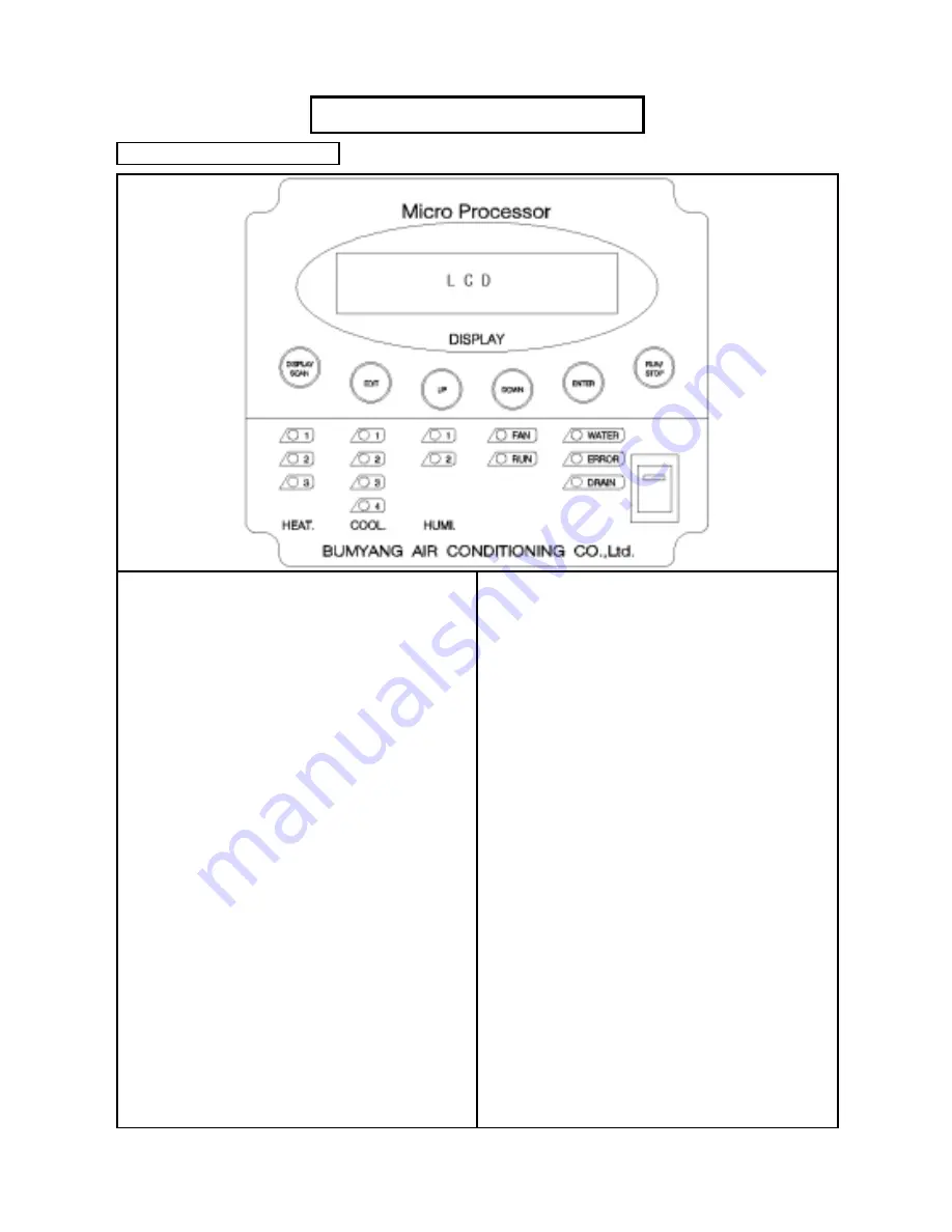
(1) RUN/STOP switch
Every time this switch is pressed,
operation shifts between stop and start
up.
(2) DISPLAY. SCAN switch
Every time this switch is pressed, present
operation status or output status is
displayed on LCD.
(3) EDIT switch
When this switch is pressed once, the
desired operating conditions is set.
Pressing this switch once more after the
desired operating condition is entered.
Then pressing this switch once more, the
desired operating condition is finished.
(4) ENTER switch
After pressing this switch, the desired
operating condition is entered. Every
time this switch is pressed, control
shifts to the next desired operating
condition.
(5) DOWN switch
Setting value decreases.
(6) UP switch
Setting value increases.
(7) POWER ON/OFF switch
Connects and disconnects the MICOM power.
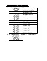
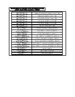
(1) RUN lamp
Lights up during operation, and goes out
when air conditioner stops.
(2) HEATER 1,2,3 lamp
Indicates one of 1, 2, and 3 heater being
operated.
(3) COMPRESSOR 1,2,3,4 lamp
Indicates one of 1, 2, 3 and 4 compressor
being operated.
- in case of compressor 1 or 2 cycle :
COMPRESSOR 1,2 lamp
- in case of compressor 3 cycle :
COMPRESSOR 1,2,3 lamp
- in case of compressor 4 cycle :
when used AHU controller
(4) HUMIDIFIER 1,2 lamp
Indicates one of 1 and 2 humidifier being
operated.
(5) WATER lamp
Indicates that water is fed into
humidifier tank. If water is not fed
within 25 seconds, system is troubled.
(6) FAN lamp
Indicate that fan operates.
(7) ERROR lamp
Indicate system failure
(8) POWER lamp
Indicates power is supplied to MICOM.
Summary of Contents for 200J
Page 10: ...Name of parts UCU 30M 50M 80M 100M UCU 150J 200J ...
Page 20: ...How to use controller ...
Page 23: ...Main Control Part ...

