background image

4

Description

4.1

Identification

4.1.1

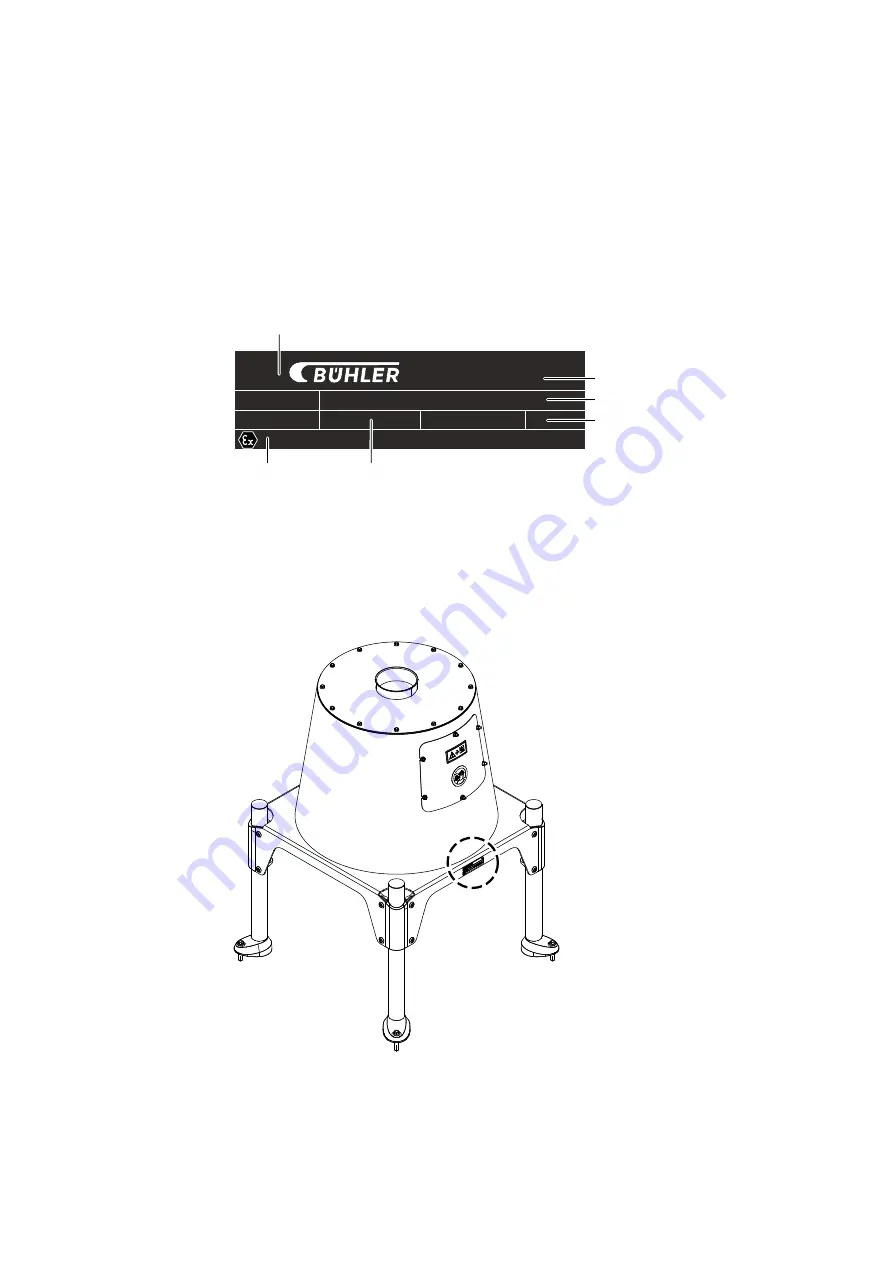
Nameplate

Model:
Serial No.:

Manufactured:

             *

(5)

(5)

(6)

(2)

(3)

(4)

(1)

Fig. 4.1

Nameplate

(1) Manufacturer

(4) Year of manufacture

(2) Address of the manufacturer

(5) Machine number

(3) Machine type

(6) ATEX marking

Position of the nameplate

Fig. 4.2


12

Bühler AG
MAYV-20150-2-1808-en-US

Chapter 4 

Description

Summary of Contents for MAYV Series

Page 1: ...Operating instructions Rotary distributor MAYV Ex Original operating instructions MAYV 20150 2 1808 en US...

Page 2: ...2 2 Technical condition 6 2 3 Personnel qualification 7 2 4 Securing against unexpected startup 7 2 5 Protective devices 7 2 6 Safety signs 7 2 7 Safe work environment 7 2 7 1 Slipping and tripping h...

Page 3: ...18 7 Commissioning 19 7 1 To be checked before commissioning 19 7 2 Inspection of EC conformity 19 8 Operation 20 8 1 Starting and stopping the machine 20 8 1 1 Starting 20 8 1 2 Starting machine aft...

Page 4: ...art of these instructions Designation Identification number Spare parts catalog 20130 1 Circuit diagram Customer specific Gearmotor Refer to the documentation supplied by the manufacturer 1 4 Contact...

Page 5: ...tend ed and passed the manufacturer s training 1 6 Presentation conventions 1 6 1 Explanation of warning messages DANGER Nature and source of the danger The danger will result in death or severe injur...

Page 6: ...a device category for the interior is therefore not re quired If the machine is identified on the nameplate as a 3D device then it is approved for operation in Zone 22 Connect the machine only to devi...

Page 7: ...not functioning effectively Before operating the machine ensure that all protective devices are function ing effectively 2 6 Safety signs If safety signs are not noticeable people are at risk Replace...

Page 8: ...rti cles can cause a fire Ensure that personnel know the fire prevention measures Prepare a water connection for extinguishing fires Keep a fire extinguisher near the machine Hang up fire prevention m...

Page 9: ...141 m3 h Conveying capacity for flour 0 5 t m3 Designation Value Unit Inlet 150 20 t h Inlet 200 40 t h Inlet 250 60 t h Conveying capacity for wheat 0 75 t m3 Designation Value Unit Inlet 150 30 t h...

Page 10: ...value LpA 70 dB A 3 5 Weights Designation Value Unit Unpackaged without supports 95 kg Unpackaged with supports 120 kg 3 6 Dimensions 40 A 670 50 580 225 D 50 800 819 600 B 35 210 C 590 Fig 3 1 A 150...

Page 11: ...Electrical specifications 3 7 1 Gearmotor Designation Value Unit Brand Nord Power consumption 0 37 kW Degree of protection IP55 Speed 29 rpm B hler AG MAYV 20150 2 1808 en US Chapter 3 Technical data...

Page 12: ...ial No Manufactured 5 5 6 2 3 4 1 Fig 4 1 Nameplate 1 Manufacturer 4 Year of manufacture 2 Address of the manufacturer 5 Machine number 3 Machine type 6 ATEX marking Position of the nameplate Fig 4 2...

Page 13: ...explosive atmosphere 4 1 3 Explanation of ATEX marking II 3D T125 C Marking Meaning ATEX symbol II Equipment group 3 External category 3 D Dust atmosphere T Maximum surface temperature in C to be expe...

Page 14: ...ributed uniformly through a rotary cylinder rotating at 29 rpm to the hoppers and thus to the outlets Because the housing is tight it requires no additional aspiration connection 4 4 EMERGENCY STOP Th...

Page 15: ...4 5 Safety signs Safety signs warn against dangers Fig 4 4 Safety signs Meaning Set the safety switches to 0 and lock them No reaching in B hler AG MAYV 20150 2 1808 en US Chapter 4 Description 15...

Page 16: ...against moisture 5 Attach here 3 Center of gravity Observe the packaging symbols 5 3 Checking delivery Check the completeness of the delivery according to the shipping note Report any missing parts or...

Page 17: ...5 5 Lifting instructions Fig 5 2 B hler AG MAYV 20150 2 1808 en US Chapter 5 Transportation 17...

Page 18: ...ing supply units 6 3 1 Connecting the electrical installation Installation and inspection work on the electrical elements of the machine may be carried out only by locally authorized specialists Conne...

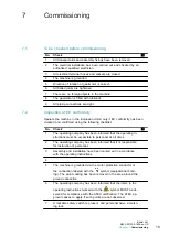
Page 19: ...operating company has been informed that the operating in structions must be accessible to personnel at all times 2 The operating company has been informed that it is responsible for instruction of p...

Page 20: ...tion for the control 2 Start product feed 8 1 2 Starting machine after EMERGENCY STOP 1 Eliminate the cause of the fault 2 Reset EMERGENCY STOP button 3 Start the machine 8 1 3 Stopping 1 Interrupt th...

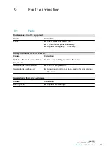
Page 21: ...s not start up Cause Correction Defect in the machine or plant con trol system See the operating manual of the control Gearmotor is not connected Connect the gearmotor Gearmotor is overheated Allow ge...

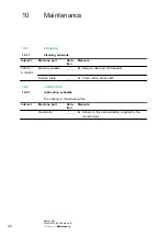
Page 22: ...__ Remove dust and dirt deposits Electric cable __ __ Clean with a damp cloth 10 2 Lubrication 10 2 1 Lubrication schedule The bearing is maintenance free Interval Machine part Dura tion Measure Gear...

Page 23: ...s personnel must be familiar with the safety precautions 11 2 Disposal 11 2 1 Disposing of operating supplies Remove operating supplies completely from the machine and dispose of them in accordance wi...

Page 24: ...B hler AG CH 9240 Uzwil Schweiz T 41 71 955 11 11 F 41 71 955 33 79 www buhlergroup com...

Reviews: