8
#2
#12 gauge cord or larger. Do not use an extension cord over 25 ft. in length.
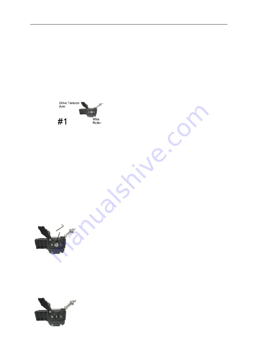
3. Install the wire roller
Before installing any welding wire into the unit, the proper sized groove must be placed into position on the wire
drive mechanism. Adjust the drive roller according to the following steps, see following picture of the wire feed
mechanism:
3.1. Open the door to the welder drive compartment.
3.2. (see #1) Loosen the tension adjusting wing nut and lifting the Drive Tension Adjustor away from the Drive
Tension Arm (see #2). Pull the drive tension arm away from the wire roller.
3.3. If there is wire already installed in
the welder, roll it back onto the wire spool by hand-turning the spool
counterclockwise. Be careful not to allow the wire to come out of the rear end of the inlet guide tube without holding
onto it or it will unspool itself. Put the end of the wire into the hole on the outside edge of the wire spool and bend it
over to hold the wire in place. Remove the spool of wire from the spool hub by removing the drive tensioning wing
nut and hardware.
3.4. Open the machine door using the “L” type six angle wrench, counterclockwise unscrewing the screw drive
roller on the wire, and remove the drive roller.
Summary of Contents for HIT140
Page 5: ...5 Assembly B FOR GASLESS WELDING ...
Page 6: ...6 C FOR GAS WELDING D FOR MMA WELDING ...
Page 21: ...21 ...
Page 22: ...22 ...


