background image

Product description

3

11

We reserve the right to make any changes due to technical modifications.

Commissioning and maintenance instructions Logano GE434 Gas-fired special boiler • Issue 02/2003

Buderus Heiztechnik GmbH • http://www.heiztechnik.buderus.de

3

Product description

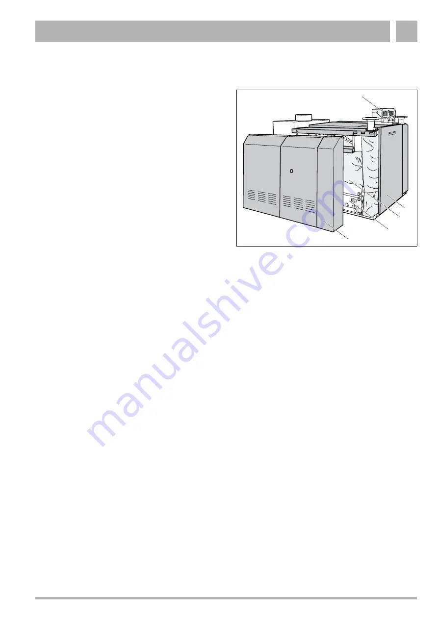
The Logano GE434 (Fig. 1) boiler comprises a r.h. and 
a l.h. boiler block, each of which is equipped with a 
separate gas burner. 

The main components of this boiler are:

Boiler blocks (Fig. 1, 

Item 5

) and gas burner (Fig. 1, 

Item 1

).

The boiler blocks transfer the heat generated by the 
burners to the heating water. 

Boiler casing (Fig. 1, 

Item 2

) and thermal insulation 

(Fig. 1, 

Item 5

).

The boiler casing and thermal insulation prevent 
energy loss. 

Control device (Fig. 1, 

Item 3

), auxiliary control 

device and two burner control units (one burner 
control unit for each burner).
The control device and the burner control unit 
monitor and control all electrical boiler components.

Fig. 1

Logano GE434

Item 1:

R.h. gas burner

Item 2:

Boiler casing

Item 3:

Control panel

Item 4:

Boiler front panel

Item 5:

R.h. boiler block with thermal insulation

3

4

1

2

5

Summary of Contents for Logano GE434

Page 1: ...6302 5450 02 2003 GB For heating engineers Please read carefully prior to installation and maintenance Commissioning and maintenance instructions Logano GE434 Gas fired special boiler ...

Page 2: ... for the safe and appropriate initial start up and maintenance of the Logano GE434 gas fired special boiler These installation and maintenance instructions are designed for specialists who due to their vocational training and experience are knowledgeable in handling heating systems and gas installations This document also refers to accessories which may be used in conjunction with the boiler insta...

Page 3: ...aks 16 5 4 Gas pipe connection 17 5 5 Electrical connection 17 6 Heating system start up 18 6 1 Commissioning 19 6 1 1 Recording gas characteristics 19 6 1 2 Making the heating system operational 19 6 1 3 Checking all gas pipes for leaks 19 6 1 4 Purging the gas supply pipe 20 6 1 5 Checking the air supply ventilation and flue pipe connections 21 6 1 6 Checking the system equipment 22 6 1 7 Starti...

Page 4: ...ent gas type 49 10 Correcting burner faults 53 10 1 Burner faults on boilers with analog burner control unit burner control unit TFI 812 53 10 2 Burner faults on boilers with digital burner control unit burner control unit MPA 50 54 11 Troubleshooting 55 11 1 Analog burner control unit 55 11 2 Digital burner control unit 57 12 Boiler operating conditions for countries outside the EU 61 12 1 Power ...

Page 5: ... for countries outside the EU on page 61 if the boiler is used in countries outside the European Union Operating conditions Dimension Notes More detailed requirements Maximum flow temperature Tmax TS C 100 120 The maximum permissible flow temperature may in compliance with national regulations be limited to a value within this range Safety limit high limit safety cut out Max possible flow temperat...

Page 6: ... 20 25 DE II2ELL3P 20 50 AT CH II2H3P 20 50 CZ II2H3P 18 37 ES GB IT PT II2H3P 20 37 GR II2H3B P 20 50 FR II2Esi3P 20 25 37 LU II2E3B P 20 50 HU II2HS3P 25 50 NL II2L3P 25 50 Tab 2 Gas categories acc to EN 437 countries of the EU Country Gas category Supply pressure in mbar BR EE I2H 20 BY CN HR RO RU SI TR UA II2H3P 20 50 SK TR II2H3P 20 37 BA BG HR TR II2H3B P 20 50 PL GZ 50 propane 20 36 Tab 3 ...

Page 7: ...ired special boiler comply with the general requirements of the Gas Equipment Directive 90 396 EWC taking EN 656 into account The requirements of the Efficiency Directive 92 42 EWC low temperature boilers are met 2 2 Notes structure Two levels of danger are identified and signified by the following symbols Further symbols identifying dangers and user notes WARNING RISK TO LIFE Identifies possible ...

Page 8: ...site between the boiler connection and the first shut off valve PLEASE NOTE Only use original Buderus components Damage caused by the use of parts not supplied by Buderus are excluded from the Buderus warranty WARNING RISK TO LIFE through the explosion of volatile gases There is a risk of explosion if you can smell gas Keep naked flames away Do not smoke Do not use lighters Avoid sparks Do not ope...

Page 9: ...on there is no mechanical air handling equipment inside the boiler room which might withdraw combustion air from the boiler room e g cooker hoods dryers ventilation equipment WARNING RISK TO LIFE through toxic flue gases Only operate these boilers with a chimney or flue gas system which supplies the stated draught during operation CAUTION SYSTEM DAMAGE through frost The heating system can freeze u...

Page 10: ...g may also prove useful sack trolley with strap 2 5 Disposal Dispose of the boiler packaging in an environmentally responsible manner Dispose of all boiler components e g boiler or control device which must be replaced via an authorised disposal site WARNING RISK TO LIFE through toxic flue gases The chimney function or the flue pipe may be faulty if the flue gas monitor trips frequently Repair the...

Page 11: ...locks Fig 1 Item 5 and gas burner Fig 1 Item 1 The boiler blocks transfer the heat generated by the burners to the heating water Boiler casing Fig 1 Item 2 and thermal insulation Fig 1 Item 5 The boiler casing and thermal insulation prevent energy loss Control device Fig 1 Item 3 auxiliary control device and two burner control units one burner control unit for each burner The control device and th...

Page 12: ... 0 243 0 269 0 296 0 323 0 350 0 377 0 404 02 Flue gas Partial load C 84 72 75 78 76 76 77 91 81 84 temperature 3 Full load C 116 104 110 117 103 109 113 116 121 124 Flue gas Partial load kg s 0 0798 0 1187 0 1146 0 1197 0 1510 0 1612 0 1671 0 1958 0 2053 0 2090 mass flow rate Full load kg s 0 0925 0 1382 0 1393 0 1405 0 1903 0 1938 0 1997 0 2398 0 2432 0 2497 CO2 content Partial load 4 0 3 1 3 7 ...

Page 13: ...o the supply pressure Boiler size Nozzle pressure LPG Butane propane mixtures B P G 30 Supply pressure Flow pressure 58 37 36 35 34 33 32 31 30 29 28 27 kW mbar mbar mbar mbar mbar mbar mbar mbar mbar mbar mbar 150 375 31 5 31 5 31 5 31 5 31 30 29 28 27 26 25 Tab 8 Nozzle pressure for LPG B P subject to the supply pressure Gas throughput Boiler size Natural gas H G20 Natural gas L G25 LPG Propane ...

Page 14: ...1 excl flue gas monitoring Only install boilers without flue gas monitoring equipment in rooms which are not part of the living accommodation of the building and which are provided with ventilation in accordance with current regulations e g boiler rooms Type B11BS incl flue gas monitoring Flue gas monitoring equipment may be required in accordance with regional or national regulations or laws e g ...

Page 15: ...tes are important for fault free operation 5 2 1 Heating return Connect the heating system return stress free to the boiler return RK Fig 2 Item 3 5 2 2 Heating flow Connect the heating system flow stress free to the boiler flow VK Fig 2 Item 2 CAUTION SYSTEM DAMAGE through leaking connections Connect the pipes without stress to the boiler connections PLEASE NOTE To prevent boiler contamination th...

Page 16: ...on Fill the heating system via the on site boiler fill and drain valve in the heating return with fill water Vent the heating system during filling Check all connections for leaks CAUTION SYSTEM DAMAGE through overpressure during leak testing Pressure control and safety equipment may be damaged through excessive pressure Ensure that when you carry out a leak test no pressure control or safety equi...

Page 17: ... off valve into the gas supply pipe Connect the gas pipe without stress to the gas connector Fig 3 Item 1 5 5 Electrical connection For details about the electrical mains supply see the boiler installation instructions chapter 7 Installing control devices Boiler size kW Gas connection 150 225 2 x Rp 225 250 375 2 x Rp 1 Tab 10 Gas connection Fig 3 Making the gas connection viewed from the back Ite...

Page 18: ...h dusty production or processing installations e g quarries mines etc Ensure that incoming combustion air is not contaminated with excessive airborne seed from composite blossom Where necessary prevent such contamination through the use of air filters CAUTION BOILER DAMAGE through contaminated combustion air Ensure adequate air supply Ensure that chlorinated cleaning agents or halogenated hydrocar...

Page 19: ...e red needle Fig 4 Item 1 of the heating system pressure gauge to the required minimum pressure of 1 bar Check the heating system water pressure see Chapter 8 6 Checking and correcting the heating system water pressure page 42 6 1 3 Checking all gas pipes for leaks Check the gas supply pipe for leaks before commissioning the heating system and confirm this step in the commissioning report Fig 4 Pr...

Page 20: ...gas train inlet must be no higher than 150 mbar 6 1 4 Purging the gas supply pipe Carry out the following steps on the l h and the r h gas burner Release the plug on the test port for gas supply pressure and venting Fig 5 Item 1 on the gas train by two turns and connect the hose Slowly open the mains gas shut off valve Purge the gas supply pipe CAUTION SYSTEM DAMAGE through short circuits Cover ar...

Page 21: ...es comply with local regulations or those stipulated by your local gas supply company Check whether the flue gas connection complies with all current regulations see Chapter 5 1 1 Flue gas connection page 14 WARNING RISK TO LIFE through poisoning Insufficient ventilation can lead to dangerous flue gas leaks Never close air ducts and vent apertures or reduce their size The boiler must not be operat...

Page 22: ...nversion see Chapter 9 Converting the boiler to a different gas type page 48 suitable for natural gas L Wobbe index for 15 C 1013 mbar Adjusted to 11 5 kWh m3 Applicable for 9 5 to 12 4 kWh m3 Wobbe index for 0 C 1013 mbar Adjusted to 12 2 kWh m3 Applicable for 10 0 to 13 1 kWh m3 HU Natural gas S G25 1 After conversion see Chapter 9 Converting the boiler to a different gas type page 48 suitable f...

Page 23: ...e Fig 6 Checking the main gas nozzle Item 1 Short version natural gas L G25 S G25 1 Item 2 Long version natural gas H G20 GZ50 or LPG 1 2 CAUTION SYSTEM DAMAGE through incorrect main gas nozzles Only commission the gas burner with correct main gas nozzles Ensure that the correct main gas nozzles have been used If necessary change the gas type see Chapter 9 Converting the boiler to a different gas ...

Page 24: ...arts Fault Any faults are indicated on the control device display Faults on boilers with analog burner control unit burner control unit TFI 812 Press the reset button Fig 8 Item 1 If the gas burner will not start after pressing the reset button several times see Chapter 11 Troubleshooting page 55 Faults on boilers with digital burner control unit burner control unit MPA 50 To reset set the ON OFF ...

Page 25: ...uge onto the test nipple Fig 9 Item 1 Check the gas supply pressure when the burner operates Record the value in the commissioning report Contact your local gas supplier if insufficient gas supply pressure Table 13 page 26 is entering your system Install a secondary gas pressure regulator upstream of the gas train if the gas supply pressure is too high Pull the test hose off again Carefully tighte...

Page 26: ...rching for leaks Never apply leak detector spray to cableways plugs or electrical leads Never let any spray drop down onto such areas Country Gas type Supply pressure Min rated Max mbar mbar mbar AT BA BE BG BR BY CH CN CZ DE DK EE ES FI FR GB GR HR IE IT LU PL PT RO RU SE SI SK TR UA Natural gas H G20 Natural gas L G25 Natural gas GZ 50 16 20 25 NL Natural gas L G25 20 25 30 HU Natural gas H G20 ...

Page 27: ...diameter AA If the flue pipe immediately downstream of the boiler is connected with a bend install the test port upstream of the bend Install the flue pipe test port Fig 10 Item 1 on the side towards the boiler For this purpose drill a 8 mm hole into the flue pipe Carry out the following tests at the flue pipe test port Insert the test probe into the core of the flue gas flow Fig 10 Recording actu...

Page 28: ...ating system inspection and maintenance page 35 Carbon monoxide content CO values in the airless state must be below 400 ppm or 0 04 vol Values above 400 ppm indicate an incorrect burner adjustment incorrect device setup burner and or heat exchanger contamination or burner faults In such cases identify and remedy all related causes WARNING RISK TO LIFE through toxic flue gases Only operate these b...

Page 29: ...e mains electrical supply e g emergency stop switch of the heating system upstream of the boiler room Remove the contact protector Fig 11 Item 2 from the monitoring lead Fig 11 Item 1 and release the plug in connector Re connect the heating system to the mains electrical supply e g switch ON the heating system emergency stop switch The solenoid valve opens after approx 12 seconds recognised by a q...

Page 30: ...test the ionisation current Record the value in the commissioning report page 33 Perfect operation requires an ionisation current of at least 2 µA when the pilot light burns without the main flame being ON A fault shutdown occurs at approx 1 µA Disconnect your heating system from the mains electricity supply Remove the test equipment Plug the monitoring lead plug in connector Fig 12 Item 3 into it...

Page 31: ...t button and hold down for approx 1 second When operating at a constant boiler temperature set the boiler water thermostat to maximum Hold the tip of the flue gas temperature sensor Fig 14 Item 1 into the core of the flue gas flow whilst the burner is operating The gas supply will be interrupted for a max of 120 seconds and the burner will be switched OFF The burner is automatically restarted 20 m...

Page 32: ...ed special boiler Issue 02 2003 Buderus Heiztechnik GmbH http www heiztechnik buderus de Heating system start up 6 6 1 11 Installing the side panels 6 1 12 Informing the system user and handing over all technical documentation Make the heating system user familiar with the boiler operation Hand over all technical documentation to the user ...

Page 33: ...n gas nozzles if necessary change over the gas type page 22 and following 6 Start up the burner page 24 7 Check the gas supply pressure flow pressure page 25 mbar 8 Check for leak during operation page 26 9 Record actual values page 27 Draught Pa Gross flue gas temperature tA C Air temperature tL C Net flue gas temperature tA tL C Carbon dioxide content CO2 or oxygen content O2 Flue gas losses qA ...

Page 34: ...alve and isolate the electrical power supply of the heating system via the boiler room main fuse or the emergency stop switch for the boiler room Close the mains gas shut off valve CAUTION SYSTEM DAMAGE through frost The heating system can freeze up if the control device has been switched OFF Protect your heating system against frost damage where temperatures below zero are expected With the contr...

Page 35: ...ontracts 8 2 Preparing the boiler for cleaning Shut down the heating system see Chapter 7 Shutting down the heating system page 34 Remove the side panels from the boiler the bottoms of which are secured with self tapping screws PLEASE NOTE You may order spare parts from the Buderus spare parts catalogue WARNING RISK TO LIFE from electric shock when the heating system is open Before you open the he...

Page 36: ...brushes Removing the gas burner Release the connection cable Fig 16 Item 5 on the intermittent ignition Fig 16 Item 4 Remove the contact protector Fig 16 Item 6 from the monitoring lead and release the plug in connector Remove the pilot gas pipe Fig 16 Item 1 from the burner shield and the gas train Fig 16 Item 2 Remove the pilot burner nozzle and air strainer and retain carefully Fig 16 Preparing...

Page 37: ...t the hot gas flues several times from the side horizontally and from above using the cleaning brush see Fig 17 and Fig 18 Remove the bottom plate Clean the combustion chamber floor and bottom plate Slide the bottom plate back in place Assemble the clean out cover of the flue gas header the thermal insulation and the boiler hoods Reinstall the gas burner in reverse order Fig 17 Removing the gas bu...

Page 38: ...ly Remove the boiler hoods thermal insulation and clean out cover of the flue gas header Remove the gas burner see Chapter 8 3 1 Cleaning the boiler with cleaning brushes page 36 Brush out severely encrusted hot gas flues see Chapter 8 3 1 Cleaning the boiler with cleaning brushes page 36 Cover the control device with foil Spray must not enter the control device Place cleaning rags onto the bottom...

Page 39: ...move the foil from the control device Fit the flue gas header clean out cover Reinstall the gas burner in reverse order Start up the boiler to dry out its interior until the boiler water has reached its maximum temperature operating selector set to manual Switch off the boiler and allow it to cool down Remove the flue gas header clean out cover Brush out the hot gas flues again after the heating s...

Page 40: ...then spray the slots from the front Position the gas burner vertically onto the burner rods Fig 21 Item 1 Spray the burner rods Fig 21 Item 1 internally with water and wait until all water has been expelled from the burner rod slots Invert the gas burner and position with the burner rod aperture pointing down to allow water to drain off Fig 22 Position the gas burner with slots pointing down to en...

Page 41: ...gas train with a test pressure of at least 100 mbar and maximum 150 mbar for internal leaks After one minute the pressure drop may be a maximum of 10 mbar Should the pressure drop be greater carry out a full leak test with foaming leak detector spray on all gas train sealing points Repeat the leak test if you discover a leak Replace the gas train if you cannot detect a leak and the pressure drop i...

Page 42: ...em 3 Then re fill the heating system with top up water Fill top up water via the on site boiler fill and drain valve in the heating return Vent the heating system Check the water pressure once more Fig 23 Pressure gauge for sealed heating systems Item 1 Red needle Item 2 Pressure gauge needle Item 3 Green field 3 1 2 PLEASE NOTE Set the system pressure to at least 1 bar when the system is cold CAU...

Page 43: ... pressure Release the plug of the test port on the burner manifold Fig 24 Item 1 by two full turns Push the test hose of the U tube pressure gauge onto the test port Fig 24 Item 1 Read off the nozzle pressure at the U tube pressure gauge and compare the actual value with those in Table 14 to Table 16 page 44 Inform the customer service department if the actual value deviates by more than 1 mbar fr...

Page 44: ...0 375 14 Tab 14 Rated gas nozzle pressure Boiler size Nozzle pressure LPG Propane P G 31 Supply pressure Flow pressure 58 37 36 35 34 33 32 31 30 29 28 27 kW mbar mbar mbar mbar mbar mbar mbar mbar mbar mbar mbar 150 375 35 34 33 32 31 30 29 28 27 26 25 Tab 15 Nozzle pressure for LPG P subject to the supply pressure Boiler size Nozzle pressure LPG Butane propane mixtures B P G 30 Supply pressure F...

Page 45: ...g system water pressure page 42 4 Check the air supply ventilation and flue pipe connections page 21 5 Check the gas supply pressure flow pressure page 25 mbar mbar 6 Check the nozzle pressure page 43 mbar mbar 7 Check for leak during operation page 26 8 Record actual values page 27 Full load Partial load Full load Partial load Draught Pa Pa Pa Pa Gross flue gas temperature tA C C C C Air temperat...

Page 46: ...derus Heiztechnik GmbH http www heiztechnik buderus de Heating system inspection and maintenance 8 Date Date Date 1 2 3 4 5 mbar mbar mbar 6 mbar mbar mbar 7 8 Full load Partial load Full load Partial load Full load Partial load Pa Pa Pa Pa Pa Pa C C C C C C C C C C C C C C C C C C ppm ppm ppm ppm ppm ppm 9 L h R h L h R h L h R h µA µA µA µA µA µA µA µA µA µA µA µA 10 11 ...

Page 47: ...rus Heiztechnik GmbH http www heiztechnik buderus de PLEASE NOTE Should you identify a condition during inspection which requires maintenance steps to be taken carry out such steps immediately in accordance with the prevailing demand Demand dependent maintenance work Page Date Date Date Date Date 1 Clean the boiler page 36 2 Clean the gas burner page 40 3 Confirm professional maintenance Company s...

Page 48: ...Replace the main gas nozzle for those used with the new gas type and use new gaskets Check the main gas nozzles by means of their designation Table 17 and Fig 25 Carry out all commissioning steps and complete the commissioning report Affix the label for the new gas type on the type plate CAUTION OPERATING FAULT through an error during gas type conversion Strictly observe the sequence of the steps ...

Page 49: ...r those used with the new gas type and use new gaskets Check the main gas nozzles by means of their designation Table 17 and Fig 25 page 48 Release the pilot gas pipe from the pilot burner and replace with the pilot burner nozzle for the new gas type pilot burner nozzle designation Table 18 Reinstall the pilot gas pipe Gas type Pilot gas nozzle designation Natural gas H G20 GZ50 5 Natural gas L G2...

Page 50: ...pare the actual value with the following values Fig 26 Checking the nozzle pressure Item 1 Test port on the burner manifold 1 Boiler size Rated gas nozzle pressure Natural gas H G 20 L G 25 S G 25 1 GZ50 mbar 150 375 14 Tab 19 Rated gas nozzle pressure Boiler size Nozzle pressure LPG Propane P G 31 Supply pressure Flow pressure 58 37 36 35 34 33 32 31 30 29 28 27 kW mbar mbar mbar mbar mbar mbar m...

Page 51: ...nti clockwise using a screwdriver Pull off the test hose and close the plug after the set value has been achieved Carry out the commissioning points 7 11 and complete the report see Chapter 6 2 Commissioning report page 33 Include all sealing points concerned with the conversion into the leak test in the operating condition Affix the label for the new gas type on the type plate PLEASE NOTE In case...

Page 52: ...g report page 33 Fig 28 Gas governor Item 1 Setting marking Item 2 Screws Item 3 Setting disc 3 2 2 1 PLEASE NOTE Conversion to a different gas type requires an appropriate adjustment of the gas governor PLEASE NOTE The gas governor settings are subject to each country s circumstances Check or correct the settings in accordance with Table 22 Country Gas type Rated supply pressure Setting mbar mbar...

Page 53: ...rner reset button through an aperture Fig 29 Item 1 in the side panel The side panel does not need to be removed Press the boiler reset button Fig 29 Item 1 Should the boiler fail to start after three attempts see Chapter 11 Troubleshooting page 55 CAUTION SYSTEM DAMAGE through frost The heating system can freeze up if the control device has been switched off Protect your heating system against fr...

Page 54: ...ults on boilers with digital burner control unit burner control unit MPA 50 Any faults are indicated on the control device display To reset set the ON OFF switch Fig 30 Item 2 to 0 OFF After waiting approx 3 minutes set the ON OFF switch Fig 30 Item 2 to I ON If the gas burner will not start after pressing the ON OFF switch several times see Chapter 11 Troubleshooting page 55 Fig 30 Logamatic 4000...

Page 55: ...pressure 10 mbar If not Check cause and remedy fault Gas supply pipe purged Purge until gas is flammable Burner warm pilot flame OK and cold burner no pilot flame If yes Replace the ignition transformer Pilot burner nozzle contaminated Blow out pilot gas pipe and nozzle Can you hear the pilot gas valve s opening click If not Check wiring and plug contacts Burner starts and enters fault state Only ...

Page 56: ...tures comply with local regulations or those stipulated by your local gas supply company In case of insufficient ventilation air immediately and permanently remedy that shortcoming Do apertures function permanently Are deposits or fibre contamination visible on the heat exchanger surface Visual check through the clean out cover and combustion chamber Carry out the dry and possibly wet cleaning pro...

Page 57: ... Has the flue gas monitor responded If the monitor responds repeatedly check the flue gas system and carry out a flue gas monitor function check Replace if faulty Initial start up Burner starts and goes into a fault state after approx 20 seconds Fault display on the control device Info The valve check system leak monitor of the burner control unit signals a gas valve leak Remedy the installation f...

Page 58: ...pprox 3 minutes after the second start Fault display on the control device No or only a very small pilot flame is recognisable Gas supply pipe purged Purge until gas is flammable Pilot gas nozzle contaminated Blow out pilot gas pipe and nozzle Burner warm pilot flame OK and cold burner no pilot flame If yes Replace intermittent ignition Can you hear the pilot gas valve s opening click If not Check...

Page 59: ... if required Is the start up load setting correct Is contamination of slots or below the burner rod slots obvious e g fluff fibres airborne seeds building dust Carry out the burner wet cleaning described in this manual Determine the source of contamination and prevent further contamination In case of airborne seed install an air filter in the inlet air supply acc to requirements Do ventilation and...

Page 60: ...ne and remedy the cause for insufficient flue draught Shut the burner down if the fault cannot be remedied immediately Negative pressure in the flue pipe 3 Pa Is the flue pipe blocked Is the size of the chimney OK Are fans used in the boiler room which extract air from the room extractor hoods dryers Are deposits or fibre contamination visible on the heat exchanger surface Visual check through the...

Page 61: ...to the type and magnitude of any deviation from the following operating conditions the operation may become prone to faults which may ultimately lead to the destruction of the boiler or individual components 12 1 Power supply conditions PLEASE NOTE Observe all standards and guidelines applicable to the operation of this system in your country Please note the details on the boiler type plate These ...

Page 62: ...ust be free from halogenated hydrocarbon compounds Identify the source of halogenated hydrocarbon compounds and eliminate their ingress Where this is impossible route combustion air from areas which are not contaminated by halogenated hydrocarbon compounds Observe the following Buderus Catalogue Heating Technology Germany Code of Practice K 3 Information Sheet No 1 of the Federal Association of th...

Page 63: ...erials Tab 25 Air supply and flue pipe Operating conditions Dimension Notes More detailed requirements General information Only use natural gas as fuel The following are amongst others not permissible Propane air mixtures Sewer gas Biogas Pit gas Methane Wobbe index WS kWh m3 n 12 0 16 1 WS at 0 C 1013 hPA Gross calorific value HS kWh m3n 9 5 13 1 Relative density 0 55 0 75 Water content dewpoint ...

Page 64: ...nia content mg m3 max 3 Tab 27 Fuel natural gas H chemical requirements Operating conditions Dimension Notes More detailed requirements Butane content in weight max 60 Gaseous constituents H2 N2 O2 CH4 in weight max 0 2 Sulphur content mg kg max 50 Supply pressure mbar 32 50 Protection against overpressure mbar max 100 The stated pressure must not be exceeded in case of faults caused by a failure ...

Page 65: ...ns Dimension Notes More detailed requirements Operating pressure overpressure bar 1 0 6 0 Permissible site test pressure bar 1 0 6 0 Protection against over temperatures via TR thermostat C 50 105 Protection against over temperatures via STB high limit safety cut out C 100 120 In some areas adjustable on site from 100 to 120 C Boiler fill water Only use drinking water to fill and top up the boiler...

Page 66: ... sales office Fig 31 Adaptor Item 1 Annular butterfly valve with actuator motor Item 2 Adaptor 1 2 Boiler Operating conditions Boiler water volume flow Operating flow temperature at burner ON Operating interruption complete boiler shutdown Min return temperature in conjunction with a Logamatic control device for modulating low temperature operation Logano GE434 No requirements No requirements Oper...

Page 67: ... 9 G Gas categories in countries of the EU 6 Gas categories in countries outside the EU 6 Gas characteristics 19 Gas connection 17 Gas governor 52 Gas throughput 13 Gas train 20 Gas type conversion 48 General operating conditions in countries of the EU 5 H Heating flow 15 Heating return 15 High limit safety cut out STB 29 I Inspection 35 Ionisation lead set 30 Ionisation monitoring 29 L List of co...

Page 68: ...erve the right to make any changes due to technical modifications Commissioning and maintenance instructions Logano GE434 Gas fired special boiler Issue 02 2003 Buderus Heiztechnik GmbH http www heiztechnik buderus de ...

Page 69: ...erve the right to make any changes due to technical modifications Commissioning and maintenance instructions Logano GE434 Gas fired special boiler Issue 02 2003 Buderus Heiztechnik GmbH http www heiztechnik buderus de ...

Page 70: ...erve the right to make any changes due to technical modifications Commissioning and maintenance instructions Logano GE434 Gas fired special boiler Issue 02 2003 Buderus Heiztechnik GmbH http www heiztechnik buderus de ...

Page 71: ...71 14 Declaration of conformity ...

Page 72: ...Buderus Heiztechnik GmbH 35573 Wetzlar http www heiztechnik buderus de e mail info heiztechnik buderus de Your local heating contractor ...

Reviews: