


Technical Specification
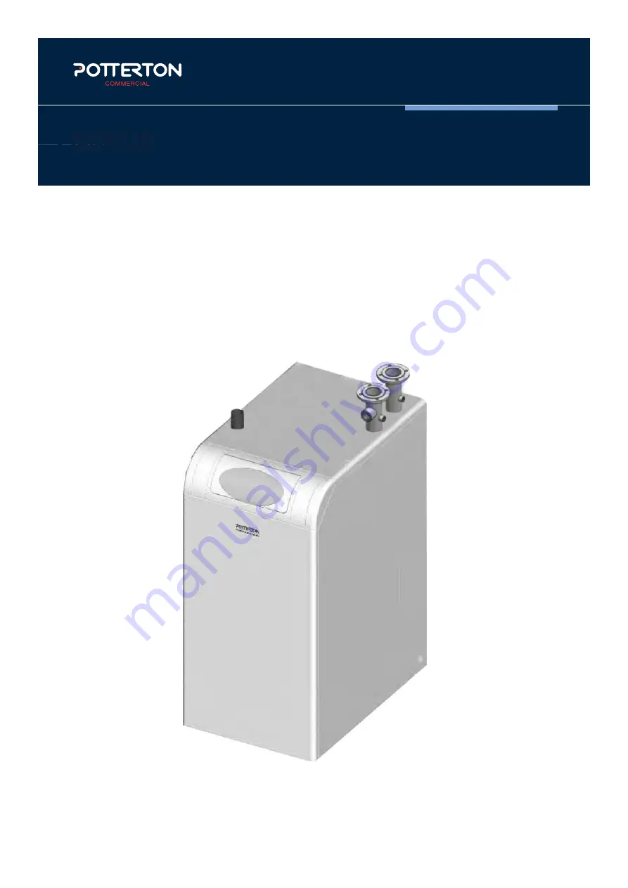
Eurocondense four
Eurocondense four
Floor standing boiler
Manufactured to the latest ISO standards, the
Eurocondense four uses tried and tested technology
to provide efficient heating for buildings of all sizes.
A range of controls are available, for easy integration
with new or existing heating systems.
Technical Specification
Works every time.
www.pottertoncommercial.co.uk
Features
Benefits
Lightweight aluminium heat exchanger.
For reliable, highly efficient heat transfer.
Top hydraulic and flue connections.
Easier to connect and less space needed for
working access.
Compact dimensions and small footprint.
Requires less space for installation.
Built in boiler control.
User friendly control panel includes operation status,
weather compensation, timer for heating and DHW,
fault diagnostics and, where relevant, cascade operation.
Controls can be programmed to work with solar thermal,
biomass and buffer tanks.
Sustainable, energy efficient, solution for a wide range
of applications.
Works every time.
sales
0345 070 1055
technical
0345 070 1057
web
pottertoncommercial.co.uk
Registered office address: Baxi Heating UK, Coventry Road, Warwick, CV34 4LL
500403
ICOM
Energy Association
RS 33961
Technical Specification
Eurocondense four
Eurocondense four
Floor standing boiler
Manufactured to the latest ISO standards, the
Eurocondense four uses tried and tested technology
to provide efficient heating for buildings of all sizes.
A range of controls are available, for easy integration
with new or existing heating systems.
Technical Specification
Works every time.
www.pottertoncommercial.co.uk
Features
Benefits
Lightweight aluminium heat exchanger.
For reliable, highly efficient heat transfer.
Top hydraulic and flue connections.
Easier to connect and less space needed for
working access.
Compact dimensions and small footprint.
Requires less space for installation.
Built in boiler control.
User friendly control panel includes operation status,
weather compensation, timer for heating and DHW,
fault diagnostics and, where relevant, cascade operation.
Controls can be programmed to work with solar thermal,
biomass and buffer tanks.
Sustainable, energy efficient, solution for a wide range
of applications.
Works every time.
sales
0345 070 1055
technical
0345 070 1057
web
pottertoncommercial.co.uk
Registered office address: Baxi Heating UK, Coventry Road, Warwick, CV34 4LL
500403
ICOM
Energy Association
RS 33961
M7248
This manual must be kept with the appliance
Direct Fired High Efficiency Boiler
Installation & Servicing Instructions
SIRIUS FS
Models
SIRIUS FS400
SIRIUS FS525


