


3
31/07/2018
ST-00000361-
BUS
J1 J2
N
P
M
344642 - 344643
EN
The device can be configured in two different ways:
-
Physical configuration
(with physical configurator connection)
-
Advanced configuration
using the appropriate configuration section on the device.
The
physical configuration
gives the user the possibility of accessing to the menu with
video door entry functions. It is the classic configuration with configurators to connect
physically to the appropriate sockets on the back of the device.
WARNING
: the configuration of the device completed using configurators CANNOT BE
MODIFIED using the menu.
N - handset number
The configurators connected to the N sockets of the device assign an identification
number within the system to each video handset . The handsets must be configured in
progressive order. The handsets must be configured in progressive order.Handsets with
parallel connection (max 3 are allowed inside apartments without item 346850) must
be configured using the same N configurator.In parallel with the main video handset,
additional handsets, video handsets and/or bells may be installed.
P – entrance panel association
The configurators connected to the P sockets of the device identify the associated EP,
which is the first entrance panel that switches itself on when the pushbutton is pressed
the first time, as well as which door lock is activated when pressing the door lock
pushbutton while the video handset is idle.
M – modalità di funzionamento
The configurators are connected to the M sockets of the device, assigning the operating
mode to the Favorites key( ) and to the Quick Actions shown on the display.
J1 – additional power supply
The JMP configurator in J1 is used to enable/disable the additional power supply
according to the following mode:
J1 CONNECTED
= Additional power supply disabled
J1 DISCONNECTED
= Additional power supply enabled
J2 - For correct operation do not remove
The
advanced configuration
has the advantage of offering many more options when
compared with the physical configuration.
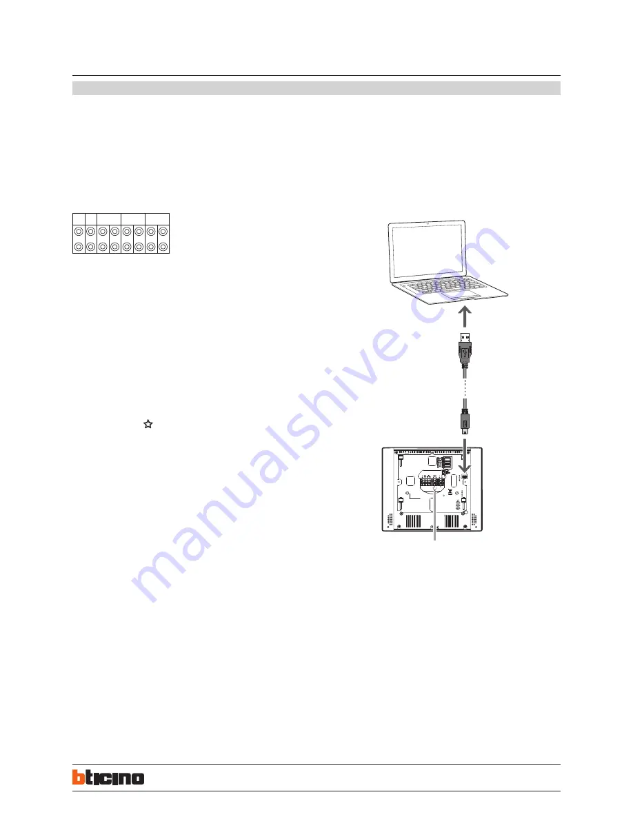
Connection to the PC
To update the firmware, connect the device to the PC using a USB-miniUSB cable.
Note: the video internal unit can also be updated via the DOOR ENTRY APP,
downloading the new firmware directly from the cloud. This procedure is only
possible after the CLASSE300X13E has been connected to a LAN (with Internet access)
and associating a smartphone.
To ensure that the communication is successful, the video internal unit must be powered.
Configuration
USB-miniUSB
CLASSE 300X13E
Touch Screen handsfree video internal units
with Wi-Fi


