


2
31/07/2018
ST-00000361-
21
24
25
26
26
22
23
27
28
29
30
Azioni rapide
10:36
Lunedì, 22 Aprile
Attivazioni
Segreteria
Telecamere
Note
Impostazioni
Intercom
Telecamera privata
Serratura
Intercom esterno
Cercapersone
1
A
z
z
i
oni rapide
Download Door Entry App
1 2
4
5 6
3
7 8 10
9
19
18
17
20
12
13
14
15
16
12
11
344642 - 344643
EN
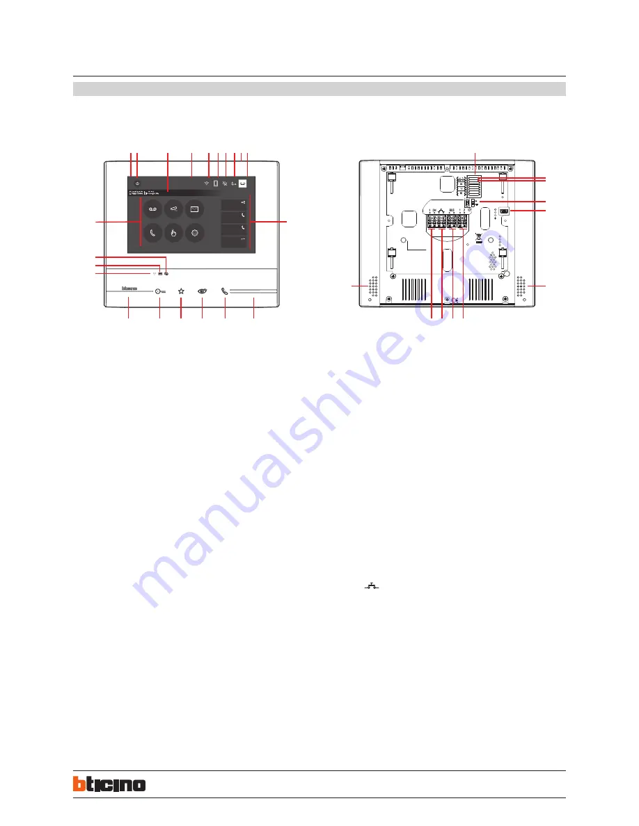
Legend
1.
17” (Touch Screen) display
2.
OFF key
3.
App:
touch to display the information page where you find a QR code that allows the
download of the DOOR ENTRY app to interact with your device
4.
Date and time
5.
Wi-Fi Connection
6.
Device/app association and enabled/disabled forwarding of call
7.
Bell exclusion
8.
Office activation
9.
Microphone
10.
Answering machine activation
11.
Quick actions
12.
Tactile guides for the blinds
13.
Connection key:
The green LED flashes to indicate an incoming call
The green LED comes on steady to indicate that there is an active call
14.
Auto-switching on/Cycling:
The red LED turns on when the key is pressed
15.
Favorites Key:
The red LED turns on when the key is pressed
(Basic configuration = STAIRCASE LIGHT. For a different configuration refer to the
physical configuration table in the following pages.)
16.
Door lock release key
The red LED turns on when the key is pressed
Nota
: the image* shows the device with all its functions enabled. Check on the
Installer Manual how to enable the functions.
* The background and icons shown may differ from those on the device.
Front view
Rear view
Note:
When the DOOR ENTRY is connected to the system (e.g. answer a call, display an Entrance Panel, etc.), no operations can be made, with the exception of the door lock release key
and Favorite Key (configured for the Staircase Light or Door Lock Direct Control functions) that continue to operate.
17.
Wi-Fi Status:
Red LED flashing = Wi-Fi is active but not connected to a network
LED off = disabled or properly functioning Wi-Fi
Green LED steady = the Classe 300X is exchanging data with the DOOR ENTRY app
(forwarding of call, auto-switching on)
18.
Message status:
Red LED flashing = new unread note/s or message/s in the answering machine
19.
Bell exclusion Status:
Red LED on = Call bell disabled
20.
Functions (only the icons for the configured functions are displayed)
21.
Configurator seat (See “Configurator Functions”)
22.
Configurator J1: remove if the additional power supply is present (clamp 1 and 2)
23.
J2 configurator: for correct operation do not remove
24.
Line termination ON/OFF micro-switch
25.
Mini USB socket for device Firmware update
26.
Loudspeaker
27.
Additional power supply clamps (1 - 2)
28.
2 WIRE SCS/BUS connection clamps
29.
Clamps (
) for the connection of an external call to the floor pushbutton
30.
dditional bell connection clamps (1 - 5M) Point-to-Point connections are required
on the clamps of the additional bells.
CLASSE 300X13E
Touch Screen handsfree video internal units
with Wi-Fi


