


55
Use Fig. 80 and Table 26 to set the DIP switches for the desired
use of the sensor.
NOTE: When an S-Bus sensor is connected to an existing net-
work, it will take 60 minutes for the network to recognize and
auto-configure itself to use the new sensor.
During the 60 minute setup period, no alarms for sensor fail-
ures (except SAT) will be issued and no economizing function
will be available.
CO
2
Sensor Wiring
When using a CO
2
sensor, the black and brown common wires
are internally connected and only one is connected to “IAQ
COM” on the W7220. Use the power from the W7220 to pow-
er the CO
2
sensor OR make sure the ground for the power sup-
plies are common. See Fig. 81 for CO
2
sensor wiring.
Fig. 81 — CO
2
Sensor Wiring
INTERFACE OVERVIEW
This section describes how to use the EconoMi$er
®
X user in-
terface for:
• Keypad and menu navigation
• Settings and parameter changes
• Menu structure and selection
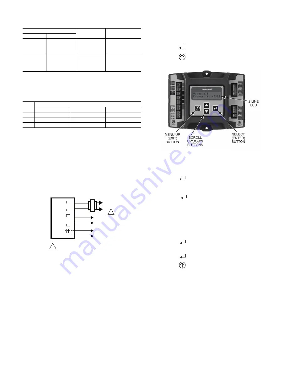
User Interface
The user interface consists of a 2-line LCD display and a 4-but-
ton keypad on the front of the economizer controller.
Keypad
Use the four navigation buttons (see Fig. 82) to scroll through
the menus and menu items, select menu items, and to change
parameter and configuration settings.
To use the keypad when working with menus:
• Press the
▲
(Up arrow) button to move to the previous
menu.
• Press the
▼
(Down arrow) button to move to the next
menu.
• Press the
(Enter) button to display the first item in the
currently displayed menu.
• Press the
(Menu Up/Exit) button to exit a menu’s item
and return to the list of menus.
Fig. 82 — W7220 Controller Navigation Buttons
To use the keypad when working with Setpoints, System and
Advanced Settings, Checkout tests and Alarms:
1. Navigate to the desired menu.
2. Press the
(Enter) button to display the first item in the
currently displayed menu.
3. Use the
▲
and
▼
buttons to scroll to the desired
parameter.
4. Press the
(Enter) button to display the value of the
currently displayed item.
5. Press the
▲
button to increase (change) the displayed
parameter value.
6. Press the
▼
button to decrease (change) the displayed
parameter value.
NOTE: When values are displayed, pressing and holding the
▲
or
▼
button causes the display to automatically increment or decre-
ment.
1. Press the
(Enter) button to accept the displayed value
and store it in nonvolatile RAM. “CHANGE STORED”
displays.
2. Press the
(Enter) button to return to the current menu
parameter.
3. Press the
(Menu Up/Exit) button to return to the previ-
ous menu.
Menu Structure
Table 27 illustrates the complete hierarchy of menus and pa-
rameters for the EconoMi$er
®
X system.
The Menus in display order are:
• STATUS
• SETPOINTS
• SYSTEM SETUP
• ADVANCED SETUP
• CHECKOUT
• ALARMS
NOTE: Some parameters in the menus use the letters MA or
MAT, indicating a mixed air temperature sensor location before
the cooling coil. This unit application has the control sensor
Table 25 — HH57AC081 Sensor Wiring Terminations
TERMINAL
TYPE
DESCRIPTION
NUMBER
LABEL
1
S-BUS
S-BUS
S-BUS
Communications
(Enthalpy Control
Sensor Bus)
2
S-BUS
S-BUS
S-BUS
Communications
(Enthalpy Control
Sensor Bus)
Table 26 — HH57AC081 Sensor DIP Switch
USE
DIP SWITCH POSITIONS FOR SWITCHES 1, 2, AND 3
1
2
3
DA
OFF
ON
OFF
RA
ON
OFF
OFF
OA
OFF
OFF
OFF
CO
2
SENSOR
24V
ANALOG
OUT
L1
(HOT)
L2
RED
BLACK
YELLOW
BROWN
ORANGE
GREEN
+
–
POWER SUPPLY. PROVIDE DISCONNECT
MEANS AND OVERLOAD PROTECTION
AS REQUIRED.
1
1
Summary of Contents for Preferred 581J04-14
Page 36: ...36 Fig 60 Integrated Gas Control IGC Board RED LED STATUS ...
Page 44: ...44 Fig 65 RTU Open Overlay for Economizer Wiring ...
Page 45: ...45 Fig 66 VFD Overlay for W2770 Controller Wiring ...
Page 100: ...100 Fig F 581J 08 09 YAC Control Diagram 208 230 3 60 460 575 3 60 APPENDIX D WIRING DIAGRAMS ...
Page 101: ...101 Fig G 581J 11YAC Control Diagram 208 230 3 60 460 575 3 60 APPENDIX D WIRING DIAGRAMS ...
Page 102: ...102 Fig H 581J 12 YAC Control Diagram 208 230 3 60 460 575 3 60 APPENDIX D WIRING DIAGRAMS ...
Page 103: ...103 Fig I 581J 04 06 YAC Power Diagram 208 230 1 60 APPENDIX D WIRING DIAGRAMS ...
Page 104: ...104 Fig J 581J 04 06 YAC Power Diagram 208 230 3 60 460 3 60 APPENDIX D WIRING DIAGRAMS ...
Page 105: ...105 Fig K 581J 04 06 YAC Power Diagram 575 3 60 APPENDIX D WIRING DIAGRAMS ...
Page 108: ...108 Fig N 581J 07 12A B C YAC Power Diagram 208 230 3 60 460 3 60 APPENDIX D WIRING DIAGRAMS ...
Page 109: ...109 Fig O 581J 07 12A B C YAC Power Diagram 575 3 60 APPENDIX D WIRING DIAGRAMS ...
Page 110: ...110 Fig P 581J 08 09 YAC Power Diagram 230 460 3 60 APPENDIX D WIRING DIAGRAMS ...
Page 111: ...111 Fig Q 581J 08 09 YAC Power Diagram 575 3 60 APPENDIX D WIRING DIAGRAMS ...
Page 112: ...112 Fig R 581J 11 YAC Power Diagram 208 230 3 60 APPENDIX D WIRING DIAGRAMS ...
Page 113: ...113 Fig S 581J 11 YAC Power Diagram 460 3 60 APPENDIX D WIRING DIAGRAMS ...
Page 114: ...114 Fig T 581J 11 YAC Power Diagram 575 3 60 APPENDIX D WIRING DIAGRAMS ...
Page 115: ...115 Fig U 581J 12 YAC Power Diagram 230 460 3 60 APPENDIX D WIRING DIAGRAMS ...
Page 116: ...116 Fig V 581J 12 YAC Power Diagram 575 3 60 APPENDIX D WIRING DIAGRAMS ...
Page 117: ...117 Fig W 581J 14 YAC Control Diagram 208 230 3 60 460 575 3 60 APPENDIX D WIRING DIAGRAMS ...
Page 118: ...118 Fig X 581J 14 YAC Power Diagram 208 230 3 60 APPENDIX D WIRING DIAGRAMS ...
Page 119: ...119 Fig Y 581J 14 YAC Power Diagram 460 3 60 APPENDIX D WIRING DIAGRAMS ...
Page 120: ...120 Fig Z 581J 14 YAC Power Diagram 575 3 60 APPENDIX D WIRING DIAGRAMS ...
Page 143: ...143 Fig AW RTU Open Wiring Diagram APPENDIX D WIRING DIAGRAMS ...


