


18
COMPRESSOR
Lubrication
The compressor is charged with the correct amount of oil at the
factory.
Replacing Compressor
NOTE: Only factory-trained service technicians should remove
and replace compressor units.
Compressor Rotation
NOTE: When the compressor is rotating in the wrong direction,
the unit makes an elevated level of noise and does not provide
cooling.
On 3-phase units with scroll compressors, it is important to be
certain compressor is rotating in the proper direction. To deter-
mine if the compressor is rotating in the proper direction:
1. Connect service gages to suction and discharge pressure
fittings.
2. Energize the compressor.
3. The suction pressure should drop and the discharge pres-
sure should rise, as is normal on any start-up.
NOTE: If the suction pressure does not drop and the discharge
pressure does not rise to normal levels, the evaporator fan is prob-
ably also rotating in the wrong direction.
4. Turn off power to the unit.
5. Reverse any two of the three unit power leads.
6. Reapply electrical power to the compressor. The suction
pressure should drop and the discharge pressure should
rise, which is normal for scroll compressors on start-up.
7. Replace compressor if suction/discharge pressures are not
within specifications for the specific compressor.
The suction and discharge pressure levels should now move to
their normal start-up levels.
Filter Drier
Replace whenever refrigerant system is exposed to atmo-
sphere. Only use factory-specified liquid-line filter driers with
working pressures no lower than 650 psig. Do not install a suc-
tion-line filter drier in liquid line. A liquid-line filter drier de-
signed for use with Puron refrigerant is required on every unit.
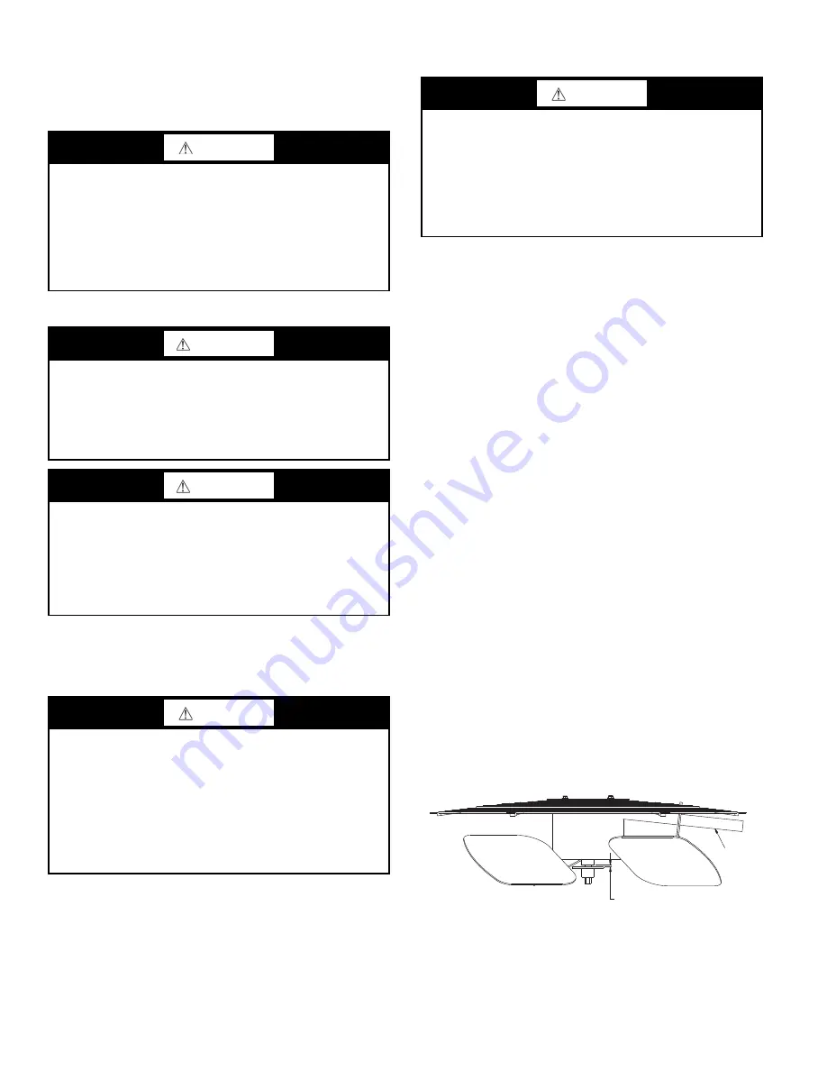
Condenser-Fan Adjustment
1. Shut off unit power supply. Install lockout tag.
2. Remove condenser-fan assembly (grille, motor, and fan).
3. Loosen fan hub setscrews.
4. Adjust fan height as shown in Fig. 30.
5. Tighten setscrews.
6. Replace condenser-fan assembly.
Fig. 30 — Condenser Fan Adjustment
See Fig. 31 for typical piping schematic.
CAUTION
UNIT DAMAGE HAZARD
Failure to follow this caution may result in damage to
components.
The compressor is in a Puron
®
refrigerant system and uses a
polyolester (POE) oil. This oil is extremely hygroscopic,
meaning it absorbs water readily. POE oils can absorb
15 times as much water as other oils designed for HCFC and
CFC refrigerants. Avoid exposure of the oil to the atmosphere.
WARNING
FIRE, EXPLOSION HAZARD
Failure to follow this warning could result in death, serious
personal injury and/or property damage.
Never use air or gases containing oxygen for leak testing or
for operating refrigerant compressors. Pressurized mixtures
of air or gases containing oxygen can lead to an explosion.
WARNING
FIRE, EXPLOSION HAZARD
Failure to follow this warning could result in death, serious
personal injury and/or property damage.
Never use non-certified refrigerants in this product. Non-
certified refrigerants could contain contaminates that could
lead to unsafe operating conditions. Use ONLY refrigerants
that conform to AHRI Standard 700.
CAUTION
INSTALLATION SITE DAMAGE
Failure to follow this caution can result in damage to equip-
ment location site.
Puron (R-410A) refrigerant contains polyolester (POE) oil
that can damage the roof membrane. Caution should be tak-
en to prevent POE oil from spilling onto the roof surface.
The factory also recommends that the suction and discharge
lines be cut with a tubing cutter instead of using a torch to
remove brazed fittings.
CAUTION
EQUIPMENT DAMAGE HAZARD
Failure to follow this caution can result in premature wear
and damage to equipment.
Scroll compressors can only compress refrigerant if rotat-
ing in the right direction. Reverse rotation for extended
times can result in internal damage to the compressor.
Scroll compressors are sealed units and cannot be repaired
on site location.
CONDUIT
0.14 in. + 0.0 / -0.03
Summary of Contents for Preferred 581J04-14
Page 36: ...36 Fig 60 Integrated Gas Control IGC Board RED LED STATUS ...
Page 44: ...44 Fig 65 RTU Open Overlay for Economizer Wiring ...
Page 45: ...45 Fig 66 VFD Overlay for W2770 Controller Wiring ...
Page 100: ...100 Fig F 581J 08 09 YAC Control Diagram 208 230 3 60 460 575 3 60 APPENDIX D WIRING DIAGRAMS ...
Page 101: ...101 Fig G 581J 11YAC Control Diagram 208 230 3 60 460 575 3 60 APPENDIX D WIRING DIAGRAMS ...
Page 102: ...102 Fig H 581J 12 YAC Control Diagram 208 230 3 60 460 575 3 60 APPENDIX D WIRING DIAGRAMS ...
Page 103: ...103 Fig I 581J 04 06 YAC Power Diagram 208 230 1 60 APPENDIX D WIRING DIAGRAMS ...
Page 104: ...104 Fig J 581J 04 06 YAC Power Diagram 208 230 3 60 460 3 60 APPENDIX D WIRING DIAGRAMS ...
Page 105: ...105 Fig K 581J 04 06 YAC Power Diagram 575 3 60 APPENDIX D WIRING DIAGRAMS ...
Page 108: ...108 Fig N 581J 07 12A B C YAC Power Diagram 208 230 3 60 460 3 60 APPENDIX D WIRING DIAGRAMS ...
Page 109: ...109 Fig O 581J 07 12A B C YAC Power Diagram 575 3 60 APPENDIX D WIRING DIAGRAMS ...
Page 110: ...110 Fig P 581J 08 09 YAC Power Diagram 230 460 3 60 APPENDIX D WIRING DIAGRAMS ...
Page 111: ...111 Fig Q 581J 08 09 YAC Power Diagram 575 3 60 APPENDIX D WIRING DIAGRAMS ...
Page 112: ...112 Fig R 581J 11 YAC Power Diagram 208 230 3 60 APPENDIX D WIRING DIAGRAMS ...
Page 113: ...113 Fig S 581J 11 YAC Power Diagram 460 3 60 APPENDIX D WIRING DIAGRAMS ...
Page 114: ...114 Fig T 581J 11 YAC Power Diagram 575 3 60 APPENDIX D WIRING DIAGRAMS ...
Page 115: ...115 Fig U 581J 12 YAC Power Diagram 230 460 3 60 APPENDIX D WIRING DIAGRAMS ...
Page 116: ...116 Fig V 581J 12 YAC Power Diagram 575 3 60 APPENDIX D WIRING DIAGRAMS ...
Page 117: ...117 Fig W 581J 14 YAC Control Diagram 208 230 3 60 460 575 3 60 APPENDIX D WIRING DIAGRAMS ...
Page 118: ...118 Fig X 581J 14 YAC Power Diagram 208 230 3 60 APPENDIX D WIRING DIAGRAMS ...
Page 119: ...119 Fig Y 581J 14 YAC Power Diagram 460 3 60 APPENDIX D WIRING DIAGRAMS ...
Page 120: ...120 Fig Z 581J 14 YAC Power Diagram 575 3 60 APPENDIX D WIRING DIAGRAMS ...
Page 143: ...143 Fig AW RTU Open Wiring Diagram APPENDIX D WIRING DIAGRAMS ...


