


6
TROUBLESHOOTING THE ECM MOTOR
Troubleshooting the X13 ECM requires a voltmeter.
1. Disconnect main power to the unit.
2. Remove the motor power plug (including the control BRN
lead) and VIO control signal lead at the motor terminals.
3. Restore main unit power.
4. Check for proper line voltage at motor power leads BLK
(at L terminal) and YEL (at N terminal). See Table 2.
5. Using a jumper wire from unit control terminals R to G,
engage motor operation. Check for 24-v output at the
defrost board terminal IFO.
6. Check for proper control signal voltages of 22-v to 28-v at
motor signal leads VIO and BRN.
7. Disconnect unit main power. Apply lockout/tag-out
procedures.
8. Reconnect motor power and control signal leads at the
motor terminals.
9. Restore unit main power.
10. The motor should start and run. If the motor does not start,
remove the motor assembly. Replace the motor with one
that has the same part number. Do not substitute with an
alternate design motor, as the torque/speed programming
will not be the same as that on an original factory motor.
REPLACING THE X-13 ECM MOTOR
Before removing the ECM belly-band mounting ring from old
motor:
1. Measure the distance from base of the motor shaft to the
edge of the mounting ring.
2. Remove the motor mounting band and transfer it to the
replacement motor.
3. Position the mounting band at the same distance that was
measured in Step 1.
4. Hand-tighten mounting bolt only. Do not tighten securely
at this time.
5. Insert the motor shaft into the fan wheel hub.
6. Securely tighten the three motor mount arms to the support
cushions and torque the arm mounting screws to 60 in.-lb
(6.8 Nm).
7. Center the fan wheel in the fan housing. Tighten the fan
wheel hub setscrew and torque to 120 in.-lb (13.6 Nm).
8. Ensure the motor terminals are located at a position below
the 3 o’clock position. Tighten the motor belly-band bolt
and torque to 80 in.-lb (9.0 Nm).
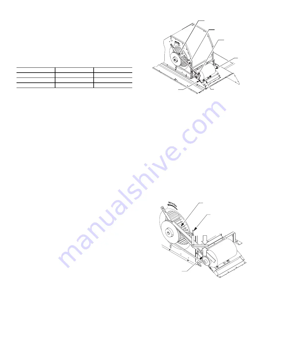
Supply Fan (Belt-Drive)
The belt-drive supply fan system consists of a forward-curved
centrifugal blower wheel on a solid shaft with two concentric
type bearings, one on each side of the blower housing. A fixed-
pitch driven pulley is attached to the fan shaft and an adjust-
able-pitch driver pulley is on the motor. The pulleys are con-
nected using a V-belt. (See Fig. 8.)
Fig. 8 — Typical Belt Drive Motor Mounting
Belt
Check the belt condition and tension quarterly. Inspect the belt
for signs of cracking, fraying, or glazing along the inside sur-
faces. Check belt tension by using a spring-force tool, such as
Browning’s “Belt Tension Checker” (P/N: 1302546 or equiva-
lent tool); tension should be 6 lb at a
5
/
8
-in. (1.6 cm) deflection
when measured at the centerline of the belt span. This point is
at the center of the belt when measuring the distance between
the motor shaft and the blower shaft.
NOTE: Without the spring-tension tool, place a straight edge
across the belt surface at the pulleys, then push down on the belt at
mid-span using one finger until a
1
/
2
-in. (1.3 cm) deflection is
reached. See Fig. 9.
Adjust belt tension by loosening the motor mounting plate
front and rear bolts and sliding the plate toward the fan (to re-
duce tension) or away from fan (to increase tension). Ensure
the blower shaft and the motor shaft are parallel to each other
(pulleys aligned). When finished, tighten all bolts and torque to
65 to 70 in.-lb (7.4 to 7.9 Nm).
Fig. 9 — Checking Blower Motor Belt Tension
REPLACING THE BELT
NOTE: Use a belt with same section type or similar size. Do not
substitute a FHP-type belt. When installing the new belt, do not
use a tool (screwdriver or pry-bar) to force the belt over the pulley
flanges as this will stress the belt and cause a reduction in belt life.
Damage to the pulley can also occur.
Use the following steps to replace the V-belt. See Fig. 8.
1. Loosen the front and rear motor mounting plate bolts.
2. Push the motor and its mounting plate towards the blower
housing as close as possible to reduce the center distance
between fan shaft and motor shaft.
Table 2 — Motor Test Volts
UNIT VOLTAGE
MOTOR VOLTAGE
MIN-MAX VOLTS
208/230
230 190-250
460
230 210-250
575
460 420-500
BLOWER PULLEY
V---BELT
MOTOR
PULLEY
MOTOR MOUNTING
PLATE
MOTOR
MOUNTING
BOLTS (4)
BROWNING BELT
TENSION CHECKER
STRAIGHTEDGE
1/2”
(1.3 cm)
BELT
DEFLECTION
Summary of Contents for Preferred 581J04-14
Page 36: ...36 Fig 60 Integrated Gas Control IGC Board RED LED STATUS ...
Page 44: ...44 Fig 65 RTU Open Overlay for Economizer Wiring ...
Page 45: ...45 Fig 66 VFD Overlay for W2770 Controller Wiring ...
Page 100: ...100 Fig F 581J 08 09 YAC Control Diagram 208 230 3 60 460 575 3 60 APPENDIX D WIRING DIAGRAMS ...
Page 101: ...101 Fig G 581J 11YAC Control Diagram 208 230 3 60 460 575 3 60 APPENDIX D WIRING DIAGRAMS ...
Page 102: ...102 Fig H 581J 12 YAC Control Diagram 208 230 3 60 460 575 3 60 APPENDIX D WIRING DIAGRAMS ...
Page 103: ...103 Fig I 581J 04 06 YAC Power Diagram 208 230 1 60 APPENDIX D WIRING DIAGRAMS ...
Page 104: ...104 Fig J 581J 04 06 YAC Power Diagram 208 230 3 60 460 3 60 APPENDIX D WIRING DIAGRAMS ...
Page 105: ...105 Fig K 581J 04 06 YAC Power Diagram 575 3 60 APPENDIX D WIRING DIAGRAMS ...
Page 108: ...108 Fig N 581J 07 12A B C YAC Power Diagram 208 230 3 60 460 3 60 APPENDIX D WIRING DIAGRAMS ...
Page 109: ...109 Fig O 581J 07 12A B C YAC Power Diagram 575 3 60 APPENDIX D WIRING DIAGRAMS ...
Page 110: ...110 Fig P 581J 08 09 YAC Power Diagram 230 460 3 60 APPENDIX D WIRING DIAGRAMS ...
Page 111: ...111 Fig Q 581J 08 09 YAC Power Diagram 575 3 60 APPENDIX D WIRING DIAGRAMS ...
Page 112: ...112 Fig R 581J 11 YAC Power Diagram 208 230 3 60 APPENDIX D WIRING DIAGRAMS ...
Page 113: ...113 Fig S 581J 11 YAC Power Diagram 460 3 60 APPENDIX D WIRING DIAGRAMS ...
Page 114: ...114 Fig T 581J 11 YAC Power Diagram 575 3 60 APPENDIX D WIRING DIAGRAMS ...
Page 115: ...115 Fig U 581J 12 YAC Power Diagram 230 460 3 60 APPENDIX D WIRING DIAGRAMS ...
Page 116: ...116 Fig V 581J 12 YAC Power Diagram 575 3 60 APPENDIX D WIRING DIAGRAMS ...
Page 117: ...117 Fig W 581J 14 YAC Control Diagram 208 230 3 60 460 575 3 60 APPENDIX D WIRING DIAGRAMS ...
Page 118: ...118 Fig X 581J 14 YAC Power Diagram 208 230 3 60 APPENDIX D WIRING DIAGRAMS ...
Page 119: ...119 Fig Y 581J 14 YAC Power Diagram 460 3 60 APPENDIX D WIRING DIAGRAMS ...
Page 120: ...120 Fig Z 581J 14 YAC Power Diagram 575 3 60 APPENDIX D WIRING DIAGRAMS ...
Page 143: ...143 Fig AW RTU Open Wiring Diagram APPENDIX D WIRING DIAGRAMS ...


