SYSTXBBECW01 &
SYSTXBBECN01
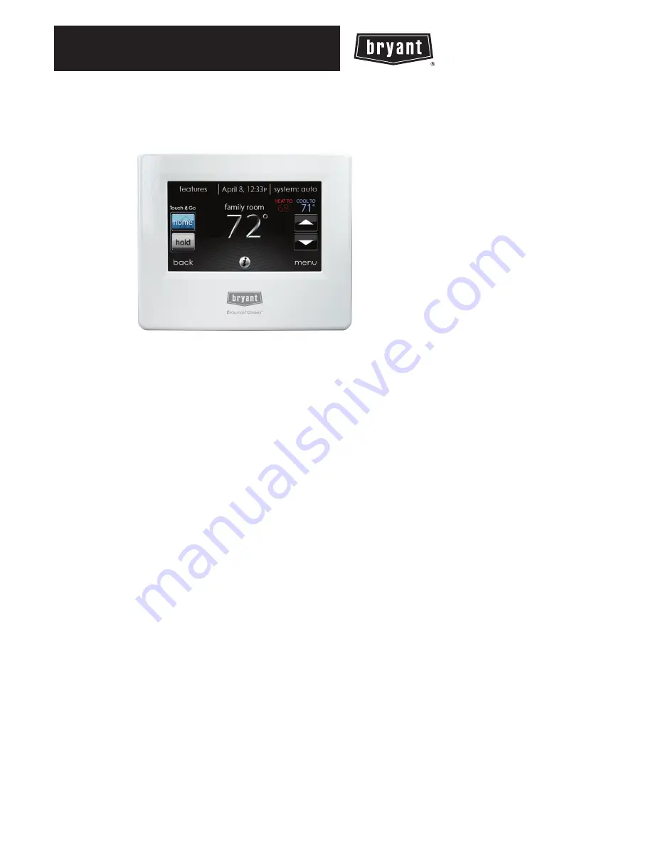
Evolution
r
Connex
t
Control
Installation Instructions
A12479
NOTE
: Read the entire instruction manual before starting the installation.
US Patents: Carrier U.S. Pat No. 7,243,004, Carrier U.S. Pat No. 7,775,452, pointSET
t
U.S.
Pat No. 7,415,102


