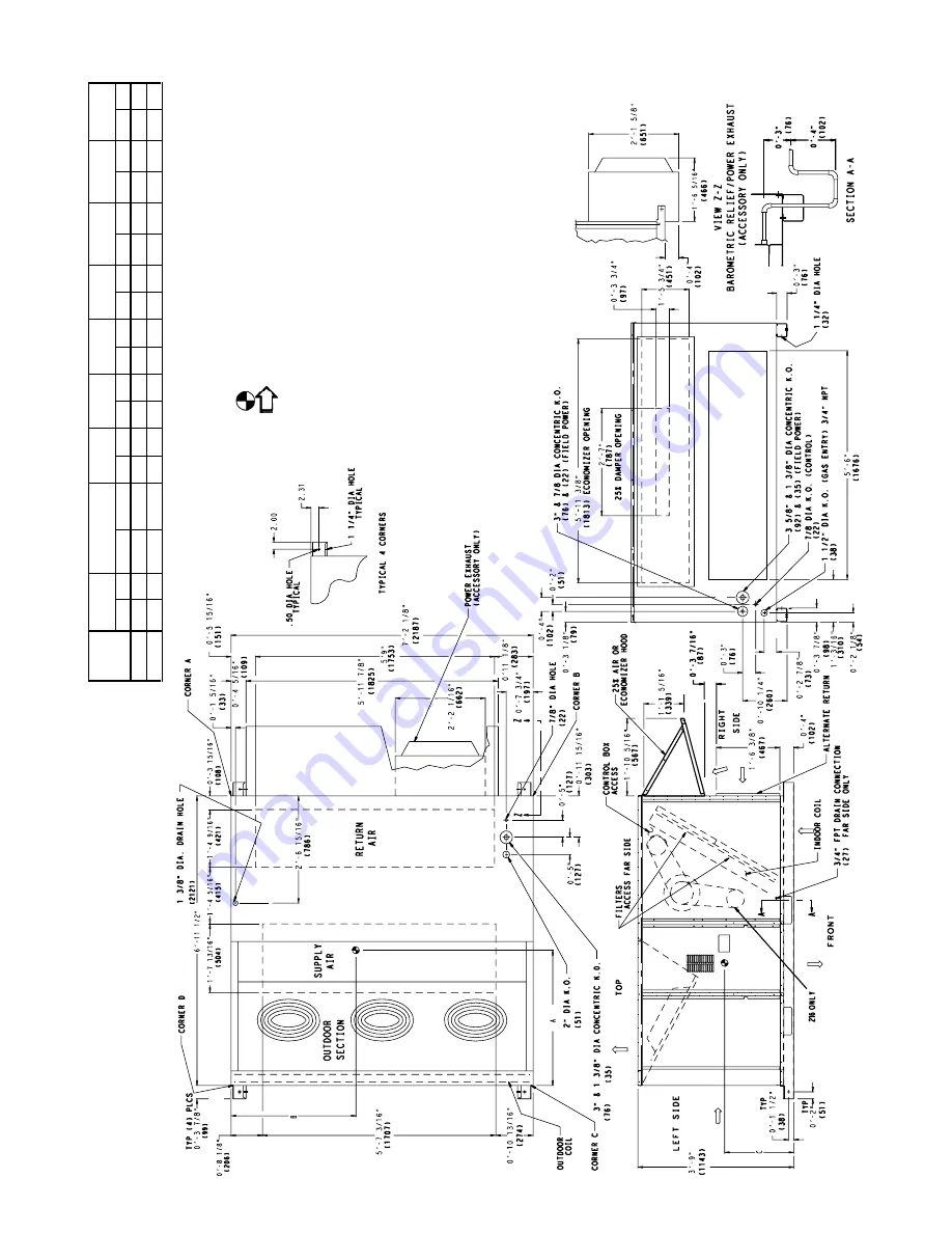
Bryant DURAPAC 579F Installation, Start-Up And Service Instructions Manual Download Page 5

5

NO

T

E

S:

1.

R

e

fe

r t

o

 p

ri

n

fo

r ro

of 

curb

 acc

e

sso

ry

 di

m

e

n

s

ions.

2

.

Dim

e

n

sio

n

s in

 (

) a

re

 in

 m

illim

e

te

rs

.

3.

C

e

n

ter

 of

 Gra

v

it

y.

4.

D

ir

e

ct

ion o

f a

irfl

o

w

.

5.

Ductwor

k

 to 

be 

atta

che

d

 to

 acce

ssor

y

 ro

of c

u

rb

 on

ly

.

6.

Mi

ni

mu

m c

le

a

ran

c

e:

•R

e

a

r:

 7

-0

 (2

134

) f

o

co

il re

mov

a

l.

 T

h

is

 di

me

nsi

o

ca

n be re

duce

d

 to

4

-0

 (12

1

9

) i

f c

ond

it

ions

 pe

rm

it co

il re

mov

a

l fro

m

 t

he 

top

.

•4

-0

 (

1

2

19)

 to

 co

mb

u

s

ti

b

le sur

fa

c

es

al

l f

o

ur si

de

(i

n

c

lu

d

e

s betw

e

e

n

un

its)

.

L

eft

 si

de

: 4

-0

 (12

1

9

) f

o

pro

per

 co

nde

nse

r co

il ai

rf

lo

w

.

F

ro

n

t: 4

-0

 (

1

219

) f

o

r con

tr

o

bo

x ac

cess

.

R

ig

ht s

ide: 

4

-0

 (

121

9) 

fo

r pr

ope

r o

pera

ti

on 

of d

a

mp

er

 and

 pow

e

r

e

x

hau

st i

so e

qui

p

p

e

d

.

•T

o

p

: 6

-0

 (1

829

) t

o

 as

sur

e

 pr

op

er 

cond

en

ser

 f

a

n op

erat

ion.

B

o

ttom

: 1

4

 (

356

) t

o

 co

mb

u

s

ti

b

le 

sur

fac

es (

w

hen

 no

t u

s

ing 

curb

).

C

o

n

tr

ol

 b

o

si

de:

 3

-0

 (91

4

to u

ngro

u

n

ded

 sur

fa

c

es

, non

-co

m

b

u

sti

b

le

.

C

o

n

tr

ol

 bo

s

id

e

: 3

-6

 (

1

0

6

7

) t

o


b

loc

k


or

 c

o

nc

re

te

 w

a

lls

, o

ot

h

e

r

gro

und

ed sur

face

s

.

L

oca

l cod

e

s o

r ju

ri

sdict

ion m

a

y pr

e

v

ail.

7.

W

ith t

he 

e

xce

pti

o

n o

f cl

e

a

ran

c

e f

o

r the

 co

nde

nse

r co

il an

d th

e d

a

m

p

e

r/

p

o

w

er

 e

x

h

a

u

s

t a

s

 st

a

ted

 i

n

 N

o

te

 #6

, a r

e

m

o

v

a

b

le


fe

nc

e

 or

 ba

rri

c

a

de

re

q

u

ire

s

 no

 cl

ea

ra

nc

e

.

8.

D

im

en

si

on

s a

re 

fro

m

 o

u

tsi

d

of c

o

rn

e

r p

o

st.

 A

llo

w

 0

-

5

/

16

 (

8

) on eac

si

d

e

fo

r t

op c

o

v

e

r dr

ip

 ed

ge.

Fig

. 4 

— B

ase

 U

n

it 

D

imen

s

ion

s

; 5

79F

180

,21

6

UNIT

ST

D U

N

IT

WE

IG

HT

E

C

ONOM

I$E

R

IV

WEI

G

HT

CO

RNER

A

CORNER

B

CORNER

C

CO

RNER

D

DIM A

D

IM

 B

D

IM 

C

lb

kg

lb

kg

lb

k

g

lb

kg

lb

kg

lb

k

g

ft-

in

.

m

m

ft

-in

.

m

m

ft-i

n

.

m

m

579

F1

80

16

50

7

4

8

9

0

4

1

4

2

3

19

2

386

1

7

5

4

03

1

8

3

4

3

8

19

9

3

-5

104

1

3

-5

10

41

1-

10

55

9

579

F2

16

18

00

8

1

6

9

0

4

1

4

3

2

19

6

410

1

8

6

4

61

2

0

9

4

7

2

21

4

3

-3

99

1

3

-7

10

92

1-

8

5

0

8

Summary of Contents for DURAPAC 579F

Page 1: ...mpressor INSTALLATION I STEP 1 PROVIDE UNIT SUPPORT A Roof Curb Assemble and install accessory roof curb or horizontal adapter roof curb in accordance with instructions shipped with this accessory See Fig 1 and 2 Install insulation cant strips roofing and counter flashing as shown Ductwork can be installed to roof curb or horizontal adapter roof curb before unit is set in place Curb or adapter roo...

Page 2: ... PKG NO REF CURB HEIGHT DESCRIPTION CRRFCURB010A00 1 2 305 Standard Curb 14 High CRRFCURB011A00 2 0 610 Standard Curb for Units Requiring High Installation CRRFCURB012A00 2 0 610 Side Supply and Return Curb for High Installation ...

Page 3: ...indoor location Do not locate unit air inlets near exhaust vents or other sources of contami nated air For proper unit operation adequate combustion and ventilation air must be provided in accordance with Sec tion 5 3 Air for Combustion and Ventilation of the National Fuel Gas Code ANSI Z223 1 American National Standards Institute Although unit is weatherproof guard against water from higher level...

Page 4: ... boards for spreader bars on all units 5 Weights do not include optional EconoMi erIV Add 90 lb 41 kg for EconoMi erIV weight 6 Weights given are for aluminum evaporator and condenser coil plate fins CAUTION All panels must be in place when rigging Fig 3 Rigging Details UNIT 579F MAXIMUM SHIPPING WEIGHT DIMENSIONS A B lb kg Ft in mm Ft in mm 180 1775 805 6 111 2 2121 3 5 1041 216 1875 850 6 111 2 ...

Page 5: ...56 to combustible surfaces when not using curb Control box side 3 0 914 to ungrounded surfaces non combustible Control box side 3 6 1067 to block or concrete walls or other grounded surfaces Local codes or jurisdiction may prevail 7 With the exception of clearance for the condenser coil and the damper power exhaust as stated in Note 6 a removable fence or barricade requires no clearance 8 Dimensio...

Page 6: ...356 to combustible surfaces when not using curb Control box side 3 0 914 to ungrounded surfaces non combustible Control box side 3 6 1067 to block or concrete walls or other grounded surfaces Local codes or jurisdiction may prevail 7 With the exception of clearance for the condenser coil and the damper power exhaust as stated in Note 6 a removable fence or barricade requires no clearance 8 Dimensi...

Page 7: ...550 1069 1287 1193 1458 1332 1550 Motor Bearing Type Ball Ball Ball Ball Maximum Allowable Rpm 1550 1550 1550 1550 Motor Pulley Pitch Diameter Low Medium Static 3 1 4 1 4 9 5 9 5 4 6 6 4 9 5 9 Min Max in High Static 3 7 4 7 4 9 5 9 5 4 6 6 4 9 5 9 Nominal Motor Shaft Diameter in 7 8 11 8 13 8 13 8 Fan Pulley Pitch Diameter in Low Medium Static 6 0 9 4 9 4 8 0 High Static 5 2 8 0 7 9 6 4 Nominal Fa...

Page 8: ...l box To install secure flue hood to access panel See Fig 9 The wind baffle is then installed over the flue hood NOTE When properly installed flue hood will line up with combustion fan housing See Fig 10 VI STEP 6 TRAP CONDENSATE DRAIN See Fig 11 for drain location One 3 4 in half coupling is pro vided inside unit evaporator section for condensate drain connection An 81 2 in x 3 4 in diameter and ...

Page 9: ...sage for elevations up to 7000 ft For elevations above 7000 ft refer to Table 4 to identify the correct orifice size for the elevation See Table 3 for the number of orifices required for each unit size Purchase these orifices from your local Bryant dealer Follow instructions in accessory Installation Instructions to install the correct orifices Table 4 LP Gas Conversion As the height above sea lev...

Page 10: ...iring dia gram and in Fig 15 NOTE For wire runs up to 50 ft use no 18 AWG American Wire Gage insulated wire 35 C minimum For 50 to 75 ft use no 16 AWG insulated wire 35 C minimum For over 75 ft use no 14 AWG insulated wire 35 C minimum All wire larger than no 18 AWG cannot be directly connected at the thermostat and will require a junction box and splice at the thermostat Set heat anticipator sett...

Page 11: ...rt bracket are secured opposite the condenser end of the unit The screens hood side panels remaining section of filter support bracket seal strip and hardware are in a package located inside the return air filter access panel Fig 18 1 Attach seal strip to upper filter retainer See Fig 19 2 Assemble hood top panel side panels upper filter retainer and drain pan see Fig 20 3 Secure lower filter reta...

Page 12: ...LY No 1 No 2 Min Max RLA LRA RLA LRA Qty Hp FLA ea Hp FLA FLA LRA FLA MCA MOCP 180 15 Tons 208 230 187 253 25 6 190 25 6 190 3 0 5 1 7 3 7 10 5 11 0 0 57 74 74 90 90 4 6 18 8 0 57 78 79 100 100 460 414 508 13 5 95 13 5 95 3 0 5 0 8 3 7 4 8 0 30 38 50 2 3 6 0 0 30 40 50 216 18 Tons 208 230 187 253 33 237 23 184 3 0 5 1 7 5 0 15 8 15 8 0 57 85 85 110 110 4 6 18 8 0 57 90 90 110 110 460 414 508 16 2 ...

Page 13: ... existing motor mount with the new motor mount provided with accessory Transformer 460 v Units Only On 460 v units a transformer is required The transformer is provided with the accessory and must be field installed Motormaster I Control Recommended mounting location is on the inside of the panel to the left of the control box The control should be mounted on the inside of the panel vertically wit...

Page 14: ...and Motors XIII STEP 13 ADJUST FACTORY INSTALLED OPTIONS A Optional EconoMi erIV See Fig 24 and 25 for EconoMi erIV component locations NOTE These instructions are for installing the optional EconoMi erIV only Refer to the accessory EconoMi erIV installation instructions when field installing an EconoMi erIV accessory To complete installation of the optional EconoMi erIV per form the following pro...

Page 15: ... in the outdoor airstream which is used to lock out the compressors below a 42 F ambient tem perature See Fig 24 Table 10 Supply Air Sensor Temperature Resistance Values DAMPER STATIC PRESSURE in wg 0 2 0 4 0 6 0 8 1 0 1 2 LEAKAGE cfm 35 53 65 75 90 102 CFM 4500 5000 5400 6000 7200 7500 9000 10 000 11 250 0 040 0 050 0 060 0 070 0 090 0 100 0 110 0 120 0 140 TEMPERATURE F RESISTANCE ohms 58 200 25...

Page 16: ...ditional acces sory return air sensor part number CRTEMPSN002A00 The accessory sensor must be mounted in the return airstream See Fig 29 In this mode of operation the outdoor air temperature is compared to the return air temperature and the lower tem perature airstream is used for cooling When using this mode of changeover control turn the free cooling enthalpy set point potentiometer fully clockw...

Page 17: ... potentiometer on the EconoMi erIV controller When using this mode of changeover control turn the enthalpy set point potentiometer fully clockwise to the D setting NOTE Remove 620 ohm resistor if differential enthalpy sen sor is installed APPLICATION ECONOMI ERIV WITH OUTDOOR AIR DRY BULB SENSOR ECONOMI ERIV WITH SINGLE ENTHALPY SENSOR Accessories Required Accessories Required Outdoor Air Dry Bulb...

Page 18: ...on When there is a call for exhaust the EconoMi erIV controller provides a 45 15 sec ond delay before exhaust fan activation to allow the dampers to open This delay allows the damper to reach the appropri ate position to avoid unnecessary fan overload Minimum Position Control There is a minimum damper position potentiometer on the EconoMi erIV controller See Fig 27 The minimum damper position main...

Page 19: ...2 9 to terminal TB2 10 When unoccupied mode is desired install a field supplied timeclock function in place of the jumper between terminals TB2 9 and TB2 10 See Fig 26 When the timeclock contacts are closed the EconoMi erIV control will be in occupied mode When the timeclock contacts are open removing the 24 v signal from terminal N the EconoMi erIV will be in unoccupied mode Demand Controlled Ven...

Page 20: ...m settings of the CO2 sensor can be changed any time after the sensor is energized Follow the steps below to change the non standard settings 1 Press Clear and Mode buttons Hold at least 5 sec onds until the sensor enters the Edit mode 2 Press Mode twice The STDSET Menu will appear 3 Use the Up Down button to toggle to the NONSTD menu and press Enter 4 Use the Up Down button to toggle through each...

Page 21: ...l ventilated area to sense average humidity 2 Route thermostat cable or equivalent single leads of colored wire from humidistat terminals through con duit in unit to the low voltage connection on the 2 pole terminal strip TB3 as shown in Fig 33 and Fig 34 See Fig 35 for operational diagram Fig 34 Typical Perfect Humidity Dehumidification Package Control Box Fig 33 Typical Wiring Perfect Humidity D...

Page 22: ... that field power connections are correct B 579F240 and 300 Only It is important to be certain the compressors are rotating in the proper direction To determine whether or not compres sors are rotating in the proper direction 1 Connect service gages to suction and discharge pres sure fittings 2 Energize the compressor 3 The suction pressure should drop and the discharge pressure should rise as is ...

Page 23: ... 13 Fan Performance 579F180 Low Heat Units LEGEND NOTES 1 Standard low medium static drive range is 891 to 1179 rpm Alternate high static drive range is 1227 to 1550 Other rpms require a field supplied drive 2 Maximum continuous bhp is 4 25 and the maximum continuous watts are 3775 Do not adjust motor rpm such that motor maximum bhp and or watts is exceeded at the maximum operating cfm 3 Static pr...

Page 24: ...0 866 3 22 2710 932 3 55 2985 994 3 88 3266 1054 4 23 3554 1111 4 57 3847 1166 4 93 4146 7 000 923 3 78 3177 985 4 11 3458 1044 4 45 3744 1100 4 80 4036 1155 5 15 4333 1207 5 51 4635 7 500 980 4 39 3690 1038 4 73 3976 1094 5 07 4267 1148 5 43 4564 1200 5 78 4864 1250 6 15 5170 8 000 1038 5 06 4251 1093 5 40 4542 1146 5 75 4838 1197 6 11 5138 1246 6 47 5443 1294 6 84 5752 8 500 1096 5 78 4859 1148 ...

Page 25: ... 2 68 2307 1259 2 91 2507 5100 904 2 04 1759 989 2 26 1952 1069 2 49 2147 1145 2 72 2345 1218 2 95 2545 1287 3 17 2749 5400 947 2 32 1999 1028 2 55 2197 1105 2 78 2396 1179 3 01 2598 1248 3 25 2802 1315 3 49 3009 5700 990 2 62 2259 1068 2 85 2461 1142 3 09 2665 1213 3 33 2871 1280 3 57 3079 1345 3 81 3289 6000 1034 2 94 2539 1109 3 18 2745 1180 3 42 2953 1248 3 67 3163 1313 3 91 3375 1376 4 16 358...

Page 26: ...watts Table 22 Perfect Humidity Dehumidification Package Static Pressure Drop in wg AIRFLOW cfm AVAILABLE EXTERNAL STATIC PRESSURE in wg 0 2 0 4 0 6 0 8 1 0 1 2 Rpm Bhp Watts Rpm Bhp Watts Rpm Bhp Watts Rpm Bhp Watts Rpm Bhp Watts Rpm Bhp Watts 7 000 992 4 05 3 348 1051 4 44 3 668 1106 4 83 3995 1160 5 24 4331 1212 5 65 4675 1262 6 08 5026 7 500 1055 4 77 3 947 1110 5 17 4 277 1162 5 58 4615 1214 ...

Page 27: ...er meet the minimum effi ciency requirements as established by the Energy Policy Act of 1992 EPACT effective October 24 1997 UNIT 579F MOTOR PULLEY TURNS OPEN 0 1 2 1 11 2 2 21 2 3 31 2 4 41 2 5 51 2 6 180 1179 1150 1121 1093 1064 1035 1006 978 949 920 891 180 1550 1522 1488 1455 1422 1389 1356 1323 1289 1256 1227 216 1095 1077 1058 1040 1021 1002 984 965 947 928 910 216 1287 1265 1243 1222 1200 1...

Page 28: ...will be ener gized and deenergized If field installed accessory CO2 sensors are connected to the EconoMi erIV control a demand controlled ventilation strategy will begin to operate As the CO2 level in the zone increases above the CO2 set point the minimum position of the damper will be increased proportionally As the CO2 level decreases because of the increase in fresh air the outdoor air damper w...

Page 29: ...ted coils be cleaned with the Totaline environmentally sound coil cleaner as described below Coil cleaning should be part of the unit s regularly scheduled maintenance procedures to ensure long life of the coil Failure to clean the coils may result in reduced durability in the environment Avoid the use of Coil brighteners Acid cleaning prior to painting High pressure washers Poor quality water for...

Page 30: ...e at the inlet of the compressor The compressor should then be run for 10 minutes shut down and the access valve opened until no oil flows This should be repeated twice to make sure the proper oil level has been achieved B Fan Shaft Bearings For size 180 units bearings are permanently lubricated No field lubrication is required For size 216 300 units lubricate bearings at least every 6 months with...

Page 31: ... tapped jacking bolt plate 7 Remove the 2 screws that secure the motor mounting plate to the motor support channel 8 Remove the 3 screws from the end of the motor sup port channel that interfere with the motor slide path 9 Slide out the motor and motor mounting plate 10 Disconnect wiring connections and remove the 4 mounting bolts 11 Remove the motor 12 To install the new motor reverse Steps 1 11 ...

Page 32: ... the charge Recheck suction pressure as charge is adjusted NOTE Indoor air cfm must be within normal operating range of unit All outdoor fans must be operating The TXV thermostatic expansion valve is set to maintain between 15 and 20 degrees of superheat at the compressors The valves are factory set and should not require re adjustment D Perfect Humidity System Charging The system charge for units...

Page 33: ...ule interrupts the control line and causes the com pressor to switch off Crankcase Heater Only the 579F300 unit and units with optional Perfect Humidity dehumidification system are equipped with a 70 watt crankcase heater to prevent absorption of liquid refrigerant by oil in the crankcase when the compressor is idle The crankcase heater is energized whenever there is a main power to the unit and t...

Page 34: ...non fused disconnect which must be in the OFF position to open the door Two doors are provided for access to the compressor compartment Two internal access doors are provided inside the filter drive access door The filter access door on the left is secured by 2 small 1 4 turn latches with folding bail type handles This door must be opened prior to opening the drive access door The drive access doo...

Page 35: ... 35 Fig 46 Typical Wiring Schematic 579F180 208 230 V Shown ...

Page 36: ... 36 Fig 47 Typical Component Arrangement 579F240 208 230 V Shown ...

Page 37: ...itor Relay LEGEND NOTES 1 Compressor and or fan motors thermally protected three phase motors protected against primary single phasing conditions 2 If any of the original wire furnished must be replaced it must be replaced with type 90 C wire or its equiv alent 3 TRAN1 is wired for 230 v operation If unit is 208 v disconnect the BLK wires from the ORN TRAN wire and reconnect to the RED TRAN wire A...

Page 38: ...ubleshooting D DCV Demand Controlled Ventilation and Power Exhaust To check DCV and Power Exhaust 1 Make sure EconoMi erIV preparation procedure has been performed 2 Ensure terminals AQ and AQ1 are open The LED for both DCV and Exhaust should be off The actuator should be fully closed 3 Connect a 9 v battery to AQ positive node and AQ1 negative node The LED for both DCV and Exhaust should turn on ...

Page 39: ... fuse or reset circuit breaker Determine cause Compressor Cycles other than normally satisfying thermostat Refrigerant overcharge or undercharge Recover refrigerant evacuate system and recharge to nameplate Defective compressor Replace and determine cause Insufficient line voltage Determine cause and correct Blocked condenser Determine cause and correct Defective overload Determine cause and repla...

Page 40: ...to increase fan speed Limit switch cycles main burners Check rotation of blower thermostat heat anticipator settings and temperature rise of unit Adjust as needed Too much outdoor air Adjust minimum position Check economizer operation Poor Flame Characteristics Incomplete combustion lack of combustion air results in Aldehyde odors CO sooting flame or floating flame Check all screws around flue out...

Page 41: ... 41 Fig 48 IGC Control Heating and Cooling LEGEND IGC Integrated Gas Unit Controller NOTE Thermostat Fan Switch in the AUTO position ...

Page 42: ...n DCV or fully open supply air signal INPUTS OUTPUTS Demand Control Ventilation DCV Enthalpy Y1 Y2 Compressor N Terminal Outdoor Return Stage 1 Stage 2 Occupied Unoccupied Damper Below set DCV LED Off High Free Cooling LED Off Low On On On On Minimum position Closed On Off On Off Off Off Off Off Low Free Cooling LED On High On On On Off Modulating between min position and full open Modulating betw...

Page 43: ... Gas piping 10 Gas pressure 1 10 Heat anticipator settings 7 10 Heat exchanger 7 High pressure switch 7 33 Hinged access doors 34 Horizontal adapter roof curb 3 Humidistat 21 Indoor air quality sensor 18 Integrated gas controller Error codes 41 Liquid propane 9 Low pressure switch 7 33 Main burners 9 28 33 Manual outdoor air damper 11 Motormaster I control 13 14 Motormaster V control 13 15 Mountin...

Page 44: ...d skills programs are available using popular video based formats and materials All include video and or slides plus companion book Classroom Service Training which includes hands on experience with the products in our labs can mean increased confidence that really pays dividends in faster troubleshooting and fewer callbacks Course descriptions and schedules are in our catalog CALL FOR FREE CATALO...

Page 45: ......

Page 46: ...Copyright 2006 Bryant Heating Cooling Systems Printed in U S A CATALOG NO 04 53579001 01 ...

Page 47: ......

Page 48: ...ERIFY THAT FAN SHEAVES ARE ALIGNED AND BELTS ARE PROPERLY TENSIONED VERIFY THAT SCROLL COMPRESSORS ARE ROTATING IN THE CORRECT DIRECTION VERIFY THAT CRANKCASE HEATER HAS BEEN ENERGIZED FOR 24 HOURS SIZE 300 AND UNITS WITH PERFECT HUMIDITY DEHUMIDIFICATION SYSTEM ONLY II START UP ELECTRICAL SUPPLY FAN AMPS EXHAUST FAN AMPS TEMPERATURES OUTDOOR AIR TEMPERATURE F DB Dry Bulb RETURN AIR TEMPERATURE F ...

Reviews: