background image

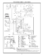
PERFORMANCE DATA (cont)

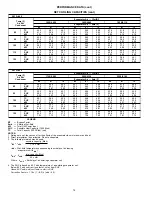
DRY COIL AIR DELIVERY* — HORIZONTAL AND DOWNFLOW DISCHARGE — UNIT SIZES 024-060

(Deduct 10% for 208 Volts)

230 AND 460 VOLT

Unit

583A

Motor Speed

External Static Pressure (in. wg)

0.0

0.1

0.2

0.3

0.4

0.5

0.6

0.7

0.8

0.9

1.0

024

Low

Watts

281

282

281

278

276

Cfm

899

828

757

691

619

Med

Watts

375

370

363

357

352

Cfm

969

897

824

744

649

High

Watts

468

457

444

431

423

Cfm

994

913

826

730

620

030

Low

Watts

246

244

243

241

Cfm

982

860

808

736

Med

Watts

343

339

336

332

328

322

317

Cfm

1233

1170

1109

1038

953

855

754

High

Watts

441

432

421

410

400

Cfm

1202

1111

1021

929

826

036

Low

Watts

470

458

445

430

415

399

384

Cfm

1463

1406

1344

1273

1188

1091

983

Med

Watts

514

501

487

471

455

438

422

Cfm

1497

1428

1348

1255

1152

1042

929

High

Watt

646

636

626

614

602

589

Cfm

1491

1412

1325

1128

1120

1003

042

Low

Watts

643

625

614

605

593

574

549

518

485

454

Cfm

1626

1614

1579

1532

1478

1421

1361

1295

1218

1120

Med

Watts

726

695

661

625

591

561

540

Cfm

1731

1672

1610

1541

1456

1345

1193

High

Watts

790

766

742

713

Cfm

1699

1602

1494

1367

048

Low

Watts

614

588

577

572

566

556

539

517

491

Cfm

1591

1549

1581

1490

1460

1421

1372

1312

1242

Med

Watts

778

756

738

719

699

676

650

623

596

572

555

Cfm

1854

1837

1804

1759

1705

1643

1577

1508

1440

1375

1315

High

Watts

896

862

829

800

775

752

728

Cfm

1956

1879

1797

1709

1615

1514

1406

060

Low

Watts

903

898

873

842

814

792

777

764

743

701

618

Cfm

2249

2220

2149

2066

1988

1923

1871

1821

1751

1632

1424

Med

Watts

1002

978

960

941

914

880

839

798

764

750

Cfm

2465

2366

2272

2181

2091

2001

1909

1815

1718

1617

High

Watts

1080

1080

1066

1041

1008

972

938

Cfm

2390

2266

2208

2144

2041

1903

1772

*Air delivery values are without air filter and are for dry coil. (See Wet Coil Pressure Drop table.)

NOTE: Deduct field-supplied air filter pressure drop and wet coil pressure drop to obtain external static
pressure available for ducting.

15

Summary of Contents for 583A Series

Page 1: ...Heat Exchangers are constructed of alumi nized steel for corrosion resistance and optimum heat transfer for improved efficiency The tubular design permits hot gases to make multiple passes across the path of the supply air In addition dimples located on the heat exchanger walls force the hot gases to stay in close contact with the walls improving heat transfer Direct Drive Multi Speed PSC Permanen...

Page 2: ...steel capable of withstanding 500 hours in salt spray Interior surfaces of the evaporator heat exchanger compartment are insulated with cleanable semi rigid insulation board which keeps the conditioned air from being affected by the outdoor ambient temperature and provides improved indoor air quality Conforms to American Society of Heating Refrig eration and Air Conditioning Engineers No 62P The s...

Page 3: ...db 67 F wb indoor entering air temperature and 95 F db outdoor entering air temperature 2 Before purchasing this appliance read important energy cost and efficiency information available from your retailer Option Code A Base Unit Wire Grille H Base Unit Louvered Grille J Unit with Wire Grille and Vinyl Coated Condenser Coil K Unit with Louvered Grille and Vinyl Coated Condenser Coil L Unit with Wi...

Page 4: ...80 1 036060 47 220 25 55 78 7 042060 47 220 15 45 78 7 036090 88 000 71 910 45 75 79 9 042090 90 000 71 910 35 65 79 9 048090 90 000 70 740 25 55 78 6 060090 90 000 70 740 25 55 78 6 048115 115 000 93 265 35 65 81 1 060115 048130 130 000 104 390 40 70 80 3 060130 LEGEND AFUE Annual Fuel Utilization Efficiency NOTE Before purchasing this appliance read important energy cost and efficiency informati...

Page 5: ...24 20 x 24 24 x 30 24 x 30 UNIT SIZE 583A 048090 048115 048130 060090 060115 060130 NOMINAL CAPACITY ton 4 4 4 5 5 5 OPERATING WEIGHT lb 421 421 421 468 468 468 COMPRESSORS Scroll Quantity 1 REFRIGERANT R 22 Quantity lb 7 2 7 2 7 2 8 1 8 1 8 1 REFRIGERANT METERING DEVICE Acutrol Device Orifice ID in 034 034 034 032 032 032 CONDENSER COIL Rows Fins in 2 17 2 17 2 17 2 17 2 17 2 17 Face Area sq ft 1...

Page 6: ...14 in round ductwork Compressor Hard Start Kit assists compressor start up by providing additional starting torque on single phase units and prolongs compressor motor life Duct Conversion Kit consists of 2 duct covers to be placed over the horizontal supply and return duct openings when the unit is converted for downshot applications Thermostats provide control for the system heating and cooling f...

Page 7: ...OPTIONS AND ACCESSORIES cont Economizer Filter Rack Manual Outside Air Damper DAMPER BLADE MANUAL OUTSIDE AIR HOOD REPLACEMENT PANEL 7 ...

Page 8: ...4 4 NEC REQ D CLEARANCES in mm Between units power entry side 42 1066 8 Unit and ungrounded surfaces power entry side 36 914 Unit and block or concrete walls and other grounded surfaces control box side 42 1066 8 UNIT 583A ELECTRICAL CHARACTERISTICS UNIT WEIGHT UNIT HEIGHT in mm A CENTER OF GRAVITY in mm lb kg X Y Z 024040 060 208 230 1 60 290 0 639 3 35 02 889 5 22 0 558 8 14 5 368 3 16 0 406 4 0...

Page 9: ...RANCES in mm Between units power entry side 42 1066 8 Unit and ungrounded surfaces power entry side 36 914 Unit and block or concrete walls and other grounded surfaces control box side 42 1066 8 UNIT 583A ELECTRICAL CHARACTERISTICS UNIT WEIGHT UNIT HEIGHT in mm A CENTER OF GRAVITY in mm lb kg X Y Z 042060 090 208 230 1 60 208 230 3 60 460 3 60 382 842 2 38 98 990 2 23 0 584 2 16 3 412 8 16 6 421 6...

Page 10: ...Seal strip must be applied as required to unit being installed 3 Dimensions in are in millimeters 4 Roof curb is made of 16 gage steel 5 Table lists only the dimensions per part number that have changed 6 Attach ductwork to curb flanges of duct rest on curb 7 Insulated panels 1 in thick fiberglass 1 lb density 8 Dimensions are in inches 3 0 4 0 BASE PAN BOTTOM SUPPLY 0 75 SIDE PANEL SUPPORT RIB S ...

Page 11: ... UNIT TO PROVIDE DESIGN CONDITION REQUIREMENTS In the Heating Capacities and Efficiencies table on page 4 note that the unit 583A 036090 will provide 71 910 Btuh with an input of 88 000 Btuh IV DETERMINE FAN SPEED AND POWER REQUIRE MENTS AT DESIGN CONDITIONS Before entering the air delivery tables calculate the total static pressure required From the given example the Wet Coil Pressure Drop Table ...

Page 12: ... 23 3 SHC 18 3 15 2 11 9 19 2 16 3 12 5 19 7 17 2 13 0 kW 2 78 2 84 2 88 2 84 2 93 2 96 2 93 3 02 3 06 583A 030 Temp F Air Ent Condenser Evaporator Air Cfm BF 875 0 138 1000 0 149 1125 0 159 Evaporator Air Ewb F 62 67 72 62 67 72 62 67 72 85 TC 27 5 30 2 32 7 28 2 30 9 33 4 28 8 31 4 33 8 SHC 24 4 20 3 16 0 26 2 21 5 16 7 27 8 22 7 17 4 kW 2 58 2 60 2 62 2 59 2 61 2 62 2 59 2 61 2 63 95 TC 26 2 29...

Page 13: ... 97 3 93 4 06 4 15 4 09 95 TC 37 6 41 6 44 9 38 3 42 0 45 1 38 7 42 0 45 1 SHC 34 4 29 0 23 0 36 6 30 3 23 5 38 7 31 3 23 8 kW 3 80 3 82 3 80 3 91 4 04 3 94 4 03 4 16 4 11 105 TC 35 9 40 0 43 6 36 6 40 3 43 7 37 3 40 3 43 6 SHC 33 6 28 4 22 5 35 6 29 7 23 0 37 3 30 8 23 4 kW 3 79 3 83 3 80 3 89 3 98 3 95 3 99 4 17 4 12 115 TC 34 2 38 2 42 0 34 9 38 5 42 1 35 8 38 5 42 0 SHC 32 7 27 7 21 9 34 9 29 ...

Page 14: ... 23 5 28 5 41 5 55 5 59 95 TC 52 2 58 0 63 7 53 2 58 5 64 1 53 9 58 4 64 0 SHC 48 2 41 0 32 7 51 8 43 2 33 6 53 9 44 8 34 2 kW 5 39 5 57 5 50 5 64 5 75 5 77 5 90 6 03 6 09 105 TC 49 1 54 4 60 4 49 9 54 9 60 7 50 9 55 0 60 5 SHC 47 3 39 4 31 5 49 9 41 6 32 4 50 9 43 5 33 0 kW 5 87 5 98 6 02 6 13 6 22 6 30 6 34 6 57 6 62 115 TC 45 9 50 2 55 2 46 8 50 3 55 5 47 3 50 2 55 3 SHC 45 3 37 4 29 4 46 8 39 ...

Page 15: ...5 593 574 549 518 485 454 Cfm 1626 1614 1579 1532 1478 1421 1361 1295 1218 1120 Med Watts 726 695 661 625 591 561 540 Cfm 1731 1672 1610 1541 1456 1345 1193 High Watts 790 766 742 713 Cfm 1699 1602 1494 1367 048 Low Watts 614 588 577 572 566 556 539 517 491 Cfm 1591 1549 1581 1490 1460 1421 1372 1312 1242 Med Watts 778 756 738 719 699 676 650 623 596 572 555 Cfm 1854 1837 1804 1759 1705 1643 1577 ...

Page 16: ...0 0 132 ECONOMIZER 1 in FILTER PRESSURE DROP in wg UNIT 583A PRESSURE DROP 024 036 0 20 042 060 0 25 OUTDOOR SOUND ONE THIRD OCTAVE BAND DATA DECIBELS UNIT 583A Frequency Hz 024 030 036 042 048 060 63 43 6 52 6 49 5 56 8 54 7 55 5 125 54 1 47 3 56 4 56 9 64 0 64 1 250 57 1 58 2 61 0 64 0 69 9 66 6 500 64 9 63 2 67 4 68 0 73 3 70 6 1000 67 6 66 1 68 1 67 7 73 5 72 6 2000 64 1 64 0 65 8 64 6 70 4 69...

Page 17: ...r Therefore heat input rate should be reduced at higher altitudes Orifices available through your distributor LIQUID PROPANE ONLY ORIFICE CONVERSION 3 5 in wg MANIFOLD PRESSURE ALTITUDE ft INPUT Btuh OUTPUT Btuh ORIFICE NUMBER 0 2000 40 000 33 200 50 57 000 47 310 46 85 500 70 965 46 115 000 95 450 42 127 000 105 410 41 2001 4500 33 290 27 630 53 47 430 39 370 50 71 150 59 050 50 95 700 79 430 45 ...

Page 18: ...TYPICAL PIPING AND WIRING Vertical Discharge Horizontal Discharge NEC National Electrical Code 18 ...

Page 19: ...he hori zontal discharge openings in the unit Units installed in horizontal discharge orientation do not require duct covers 4 Airflow Units are draw thru in the Cooling mode and blow thru in the Heating mode 5 Maximum cooling airflow To minimize the possibility of condensate blow off from the evaporator airflow through the units should not exceed 450 cfm ton 6 Minimum cooling airflow The minimum ...

Page 20: ...s Fuse or HACR Breaker NOTES 1 In compliance with NEC National Electrical Code requirements for multimotor and combination load equipment refer to NEC Articles 430 and 440 the overcurrent protective device for the unit shall be fuse or HACR breaker The CGA Canadian Gas Association units may be fuse or circuit breaker 2 Minimum wire size is based on 60 C copper wire If other than 60 C wire is used ...

Page 21: ...sformer Field Splice Terminal Marked Terminal Unmarked Splice Splice Marked Factory Wiring Field Control Wiring Field Power Wiring Accessory or Optional Wiring To Indicate Common Potential Only Not to Represent Wiring NOTES 1 If any of the original wires furnished are replaced it must be replaced with type 90 degree C wire or its equivalent 2 See Trade Prices for thermostat and subbases 3 Use 75 d...

Page 22: ...Outdoor Fan Motor QT Quadruple Terminal RS Rollout Switch SEN Sensor SW Switch TRAN Transformer Field Splice Terminal Marked Terminal Unmarked Splice Splice Marked Factory Wiring Field Control Wiring Field Power Wiring Accessory or Optional Wiring To Indicate Common Potential Only Not to Represent Wiring NOTES 1 If any of the original wires furnished are replaced they must be replaced with type 90...

Page 23: ...tdoor Fan Motor QT Quadruple Terminal RS Rollout Switch SEN Sensor SW Switch TRAN Transformer Field Splice Terminal Marked Terminal Unmarked Splice Splice Marked Factory Wiring Field Control Wiring Field Power Wiring Accessory or Optional Wiring To Indicate Common Potential Only Not to Represent Wiring NOTES 1 If any of the original wires furnished are replaced they must be replaced with type 90 d...

Page 24: ... indoor evapo rator fan relay IFR The normally open contacts of C close and complete the circuit through compressor motor COMP to outdoor condenser fan motor OFM Both motors start in stantly The set of normally open contacts of IFR close and com plete the circuit through IFM The IFM starts instantly On the loss of the thermostat call for cooling 24 v is removed from both the Y and G terminals prov...

Page 25: ...or air cavity section 5 Unit shall have a field supplied condensate trap C Fans 1 The evaporator fan shall be 3 speed direct drive as shown on equipment drawings 2 Fan wheel shall be made from steel and shall be double inlet type with forward curved blades with cor rosion resistant finish Fan wheel shall be dynamically balanced 3 Condenser fan shall be direct drive propeller type with aluminum bla...

Page 26: ...cooling in addi tion manual or automatic changeover and indoor fan control 7 Natural to Propane Conversion Kit Shall be complete with all required hardware to con vert to liquid propane LP operation at 3 5 in wg manifold pressure 8 Low Ambient Package Shall consist of a solid state control and condenser coil temperature sensor for controlling condenser fan motor operation which shall allow unit to...

Page 27: ......

Page 28: ...Copyright 1999 Bryant Heating Cooling Systems SPECIFICATIONS SUBJECT TO CHANGE WITHOUT NOTICE UNIT MUST BE INSTALLED IN ACCORDANCE WITH INSTALLATION INSTRUCTIONS Printed in U S A 4 99 5258 300 ...

Reviews: