


40
PERSONAL INJURY HAZARD
Failure to follow this WARNING can result in
personal injury.
Disconnect all electrical power when servicing the fan
motor. Apply appropriate lockout/tagout procedures.
!
WARNING
3. Shut off power to the unit and install a lockout tag..
4. Disconnect the gas piping at the unit gas valve.
5. Remove the wires connected to the gas valve. Mark
each wire to assist in reconnecting power to the gas
valve.
6. Remove the igniter wires and sensor wires at the Inte-
grated Gas Unit Controller (IGC). See Fig. 55.
7. Remove the 2 screws that attach the burner rack to
the vestibule plate. See Fig. 51.
BURNER
ASSEMBLY
GAS VALVE
VESTIBULE
PLATE
SCREWS
MANIFOLD
PRESSURE TAP
~
C12594
Fig. 51
−
Burner Assembly Removal
3
2
1
1
C09395
Item No.
Description
1
Gas manifold mounting screws
(
qty 2)
2
Gas valve inlet plug
3
Propane conversion label
(apply label where indicated)
4
Gas manifold pressure tap
Fig. 52
−
Burner Tray Details
8. Slide the burner tray out of the unit (Fig. 52).
9. To reinstall, reverse the procedure outlined above.
Cleaning and Adjustment
1. Remove the burner rack from the unit as described in
the Removal and Replacement of Gas Train section.
2. Inspect the burners; if dirty, remove the burners from
rack. (Mark each burner to identify its position before
removing from the rack.)
3. Use a soft brush to clean the burners and cross
−
over
port as required.
4. Adjust the spark gap. The gap should be 0.12 – 0.14
″
(3.06 – 3.60 mm) and spaced 0.18
″
(4.60 mm) from
the end of the burner. (See Fig. 54)
5. If the factory orifice has been removed, check that
each orifice is tight at its threads into the manifold
pipe and the orifice projection does not exceed the
maximum valve. See Fig. 50.
6. Reinstall burners on rack in the same locations as
they were installed at the factory. The outside cross-
over flame regions of the outermost burners are
pinched off to prevent excessive gas flow from the
side of the burner assembly. If the pinched crossovers
are installed between two burners, the flame will not
ignite properly.
7. Reinstall the burner rack as described in the Removal
and Replacement of Gas Train section.
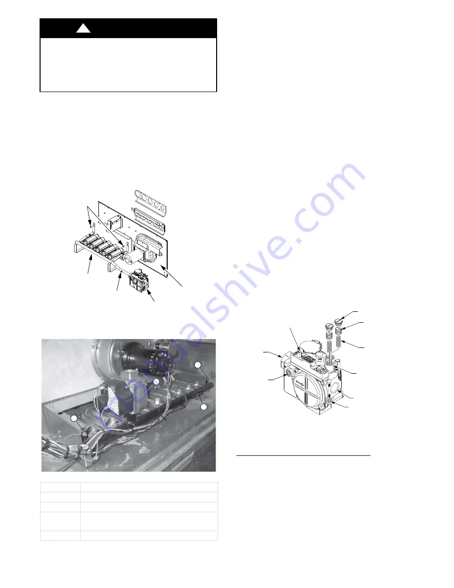
Gas Valve
All unit sizes are equipped with 2
−
stage gas valves. See
Fig. 53 for locations of adjustment screws and features.
PLASTIC ADJUST
SCREW (2)
REGULATOR SPRING (2)
(PROPANE - WHITE
NATURAL - SILVER)
LOW STAGE
GAS PRESSURE
REGULATOR
ADJUSTMENT
MANIFOLD
PRESSURE TAP
INLET
PRESSURE TAP
ON/OFF
SWITCH
REGULATOR
COVER SCREW (2)
NPT INLET
NPT OUTLET
C12066A
Fig. 53
−
Gas Valve
Adjusting Gas Valve Pressure Settings
IMPORTANT
: Leak check (using a mixture of soapy
water or leak detection fluid) all gas connections
including the main service connection, gas valve, gas
spuds, and manifold pipe plug. All leaks must be repaired
before firing the unit.
Summary of Contents for 581J-17-28
Page 73: ...73 APPENDIX IV WIRING DIAGRAMS cont C160042 Fig 72 581J D17 D28 Power Diagram 208 230 3 60 ...
Page 74: ...74 APPENDIX IV WIRING DIAGRAMS cont C160043 Fig 73 581J D17 D28 Power Diagram 460 3 60 ...
Page 75: ...75 APPENDIX IV WIRING DIAGRAMS cont C160044 Fig 74 581J D17 D28 Power Diagram 575 3 60 ...
Page 80: ...80 APPENDIX IV WIRING DIAGRAMS cont C160049 Fig 79 RTU OPEN Wiring Diagram ...


