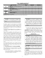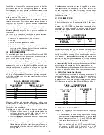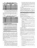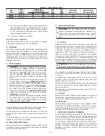
NOTE:
Read the entire instruction manual before starting the
installation.
TABLE OF CONTENTS
SAFETY CONSIDERATIONS .....................................................1
INTRODUCTION ..........................................................................2
LOCATION....................................................................................2
General ......................................................................................2
Location Relative to Cooling Equipment ................................3
INSTALLATION ...........................................................................3
Air for Combustion and Ventilation ........................................3
General ......................................................................................3
Unconfined Space .....................................................................4
Confined Space .........................................................................4
START-UP, ADJUSTMENT, AND SAFETY CHECKOUT ......7
Operational Checkout ...............................................................7
Combustion Check....................................................................7
Fan Adjustment Check ...........................................................10
Limit Control Check...............................................................10
For Year-Round Air Conditioning .........................................10
Heating ....................................................................................10
Cooling ....................................................................................10
Constant Blower Switch .........................................................10
MAINTENANCE.........................................................................10
General ....................................................................................10
Oil Burner ...............................................................................11
Heat Exchanger and Flue Pipe ...............................................11
Blower Removal .....................................................................11
SAFETY CONSIDERATIONS
FOR YOUR SAFETY
DO NOT STORE OR USE GASOLINE OR OTHER
FLAMMABLE VAPORS AND LIQUIDS IN THE VI-
CINITY OF THIS OR ANY OTHER APPLIANCE.
DO NOT ATTEMPT TO START THE BURNER
WHEN EXCESS OIL HAS ACCUMULATED, WHEN
THE FURNACE IS FULL OF VAPOR, OR WHEN
THE COMBUSTION CHAMBER IS VERY HOT.
WARNING:
For use with grade 1 or 2 Fuel Oil. Do not
use Gasoline, Crankcase Oil, or any Oil containing
Gasoline! Failure to follow this warning could lead to
sooting, fire, explosion, and/or severe bodily harm.
CAUTION:
Never burn garbage or paper in the heating
system and never leave rags, paper, or any flammable
items around the unit.
CAUTION:
These instructions are intended to be used
by qualified personnel who have been trained in installing
this type of furnace. Installation of this furnace by an
unqualified person may lead to equipment damage and/or
a hazardous condition which may lead to bodily harm.
All local and national code requirements governing installation of
oil burning equipment, wiring, and flue connections must be
followed. Some of the codes (issued by the Canadian Standards
Association, the National Fire Protection Agency, and/or the
American National Standards Institute) that may be applicable are:
ANSI/NFPA 31: INSTALLATION OF OIL BURNING EQUIP-
MENT
ANSI/NFPA 211: CHIMNEYS, FIREPLACES, VENTS, AND
SOLID FUEL BURNING APPLIANCES
ANSI/NFPA 90B: WARM AIR HEATING AND AIR CONDI-
TIONING SYSTEMS
ANSI/NFPA 70: NATIONAL ELECTRICAL CODE
CSA B139: INSTALLATION CODE FOR OIL BURNING
EQUIPMENT
CAS C22.1: CANADIAN ELECTRICAL CODE
Only the latest issues of these codes should be used, and are
available from either The National Fire Protection Agency, Bat-
terymarch Park, Quincy, MA 02269 or The Canadian Standards
Association, 178 Rexdale Blvd., Rexdale, Ontario M9W 1R3
Recognize safety information. This is the safety-alert symbol
When you see this symbol on the furnace and in instructions or
manuals, be alert to the potential for personal injury.
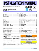
Fig. 1—369RAN Multipoise Oil Furnace
A97247
installation, start-up,
and operating instructions
MULTIPOISE
OIL FURNACE
Cancels:
New
II 369R-70-1
12-00
369RAN
Series A
—1—


