background image

18

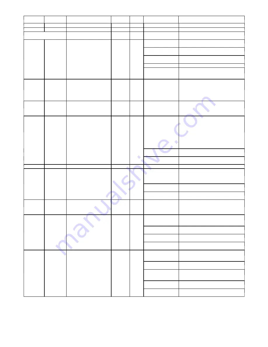
Table 6—Fault Code Actions

Flash

Code

Type

Amber LED Description

Reset

Time

Mode

Possible Causes

Actions

ON, no flash

Standby

1, pause

Variable Capacity

1 (2 sec ON), longer pause

(1 second OFF)

Variable Capacity

(Range Cutback)

25

System Mal-

function

INVALID MODEL

PLUG/INVERTER SIZE

NA

Both

Wrong Model Plug In-

stalled

Verify correct model plug installed

Damaged Model Plug

Check model plug for corrosion or breakage;

replace if necessary

Missing model plug on

service board

Re-install original model plug

Damaged AOC control

Replace AOC control

Incorrect Model Plug

with Inverter Size

Replace plug or inverter with correct size (If

model plug is for 2 Ton but Inverter is 3 Ton,

fault code 25 will be shown)

31

Local

HIGH PRESSURE SWITCH

OPEN

(stage/speed down for each

occurrence, elevates to fault

code 84 when it occurs while

running on the lowest stage)

6 Minutes

(then re-

duced

stage oper-

ation)

Both

High Pressure Event

System will self-mitigate by reducing the stage,

persistent conditions will lead to lockout (refer

to Error Code 84). 2 hours of accumulated

operation without further fault will reset fault

reduced stage operation.

32

Local

LOW PRESSURE TRIP

(elevates to fault code 83 after

3 occurrences)

6 Minutes

Both

Low Pressure Event

System will self-mitigate, persistent conditions

will lead to lockout (refer to Error Code 83) 2

hours of accumulated operation without further

fault will reset fault counter

33

Local

LOST INVERTER COMMUNI-

CATIONS

(Occurs aftr 2 minutes of no

communications between AOC

and MOC)

(Elevates to fault code 48 after

3 consecutive failures within 20

minute or 20 minutes continu-

ous loss of connection)

NA

Both

Loose or disconnected

harness (Hardness be-
tween AOC (PL20) and

MOC)

Verify good harness connection

Radio or Electrical noise

System will try to self-mitigate with repeated

start attempts

Possible damage to in-

verter

change out the Inverter drive

46

Local

BROWNOUT EVENT

6 Minutes

Both

low line voltages

if persistent contact power provider

48

System

Malfunction

LOST INVERTER COMMUNI-

CATIONS

(Elevated from fault code 33 af-

ter 3 occurrences)

NA

Both

Loose or disconnected

harness (Hardness be-
tween AOC (PL20) and

MOC)

Verify good harness connection

Radio or Electrical noise

System will try to self-mitigate with repeated

start attempts

Possible damage to in-

verter

change out the Inverter drive

49

Local

COMPRESSOR OVER CUR-

RENT FAULT

(Elevates to fault code 95 after

5 occurrences)

6 Minutes

Both

Refer to fault code 95

Refer to fault code 95

53

Fault

OUTDOOR AIR TEMP

SENSOR FAULT

NA

Both

Sensor Harness not

connected to AOC con-

trol

Ensure plug is connected to AOC control

Broken or loose har-

ness wire

Check harness for continuity; see resistance

chart to check resistance at given temperature

Broken or Damaged

Sensor

Check harness for continuity; see resistance

chart to check resistance at given temperature

Hardware damage to

AOC control

Replace AOC control

54

Fault

SUCTION TEMP SENSOR

FAULT

NA

Both

Sensor Harness not

connected to AOC

control

Ensure plug is connected to AOC control

Broken or loose

harness wire

Check harness for continuity; see resistance

chart to check resistance at given temperature

Suction Thermistor not

properly attached or in

wrong location

Ensure Sensor is properly attached to the ac-

cumulator entry-tube

Broken or Damaged

Sensor

Check harness for continuity; see resistance

chart to check resistance at given temperature

Hardware damage to

AOC control

Replace AOC control

Summary of Contents for 189BNV EVOLUTION

Page 1: ...ROUBLESHOOTING 9 13 Service Tool 14 31 System Communication Failure 14 Model Plug 14 Status Codes 14 Variable Speed Compressor Winding Resistance 14 Fan Motor 15 Control Fault 15 Brown Out Protection 15 230v Line Power Disconnect Detection 15 Pressure Switch Protection 15 Suction Pressure Transducer SPT 15 Temperature Thermistors 16 Fault Code Action Table 18 Variable Speed Drive LED Location and ...

Page 2: ...tion Series 8 18 SEER B Puron N 208 230 1 or 208 230 1 V Variable Speed 0 Not Defined 0 Not Defined 0 Not Defined A Original Series MODEL NUMBER NOMENCLATURE AIR CONDITIONER 1 2 3 4 5 6 7 8 9 10 11 12 14 N N N A A N N N N N A N A N N A 1 8 9 B N V 0 3 6 0 0 0 A Product Family Tier SEER Major Series Voltage Variations Cooling Capacity Open Open Open Series 1 AC 8 Evolution Series 9 19 SEER B Puron ...

Page 3: ...ee the Long Line Guideline for details Maximum Total Equivalent Length Outdoor Unit BELOW Indoor Unit Size Liquid Line Diameter w TXV HP with Puronr Refrigerant Maximum Total Equivalent Length Vertical Separation ft m Outdoor unit BELOW indoor unit 0 20 0 6 1 21 30 6 4 9 1 31 40 9 4 12 2 41 50 12 5 15 2 51 60 15 5 18 3 61 70 18 6 21 3 71 80 21 6 24 4 1 Ton 3 8 100 100 100 100 100 100 100 2 Ton 3 8...

Page 4: ...ronr WARNING CUT HAZARD Failure to follow this caution may result in personal injury Sheet metal parts may have sharp edges or burrs Use care and wear appropriate protective clothing and gloves when handling parts CAUTION Refrigeration systems contain refrigerant under pressure Extreme caution should be observed when handling refrigerants Wear safety glasses and gloves to prevent personal injury D...

Page 5: ...ed operating temperatures especially if aluminum conductors are used Unit Electrical Power Power wires from the unit s disconnect should be routed through the power wiring hole provided at the bottom of the unit s control box Connect the ground wire to the ground connection in the control box and connect the power wiring to the terminal block as shown on the wiring and Installation Instructions su...

Page 6: ... by the control board for a 0 to 200 psig range of pressure at the suction tube This interpreted pressure data is then intelligently used by the AOC control board for low pressure cut out loss of charge management compressor protection oil circulation management lubrication management and EXV control Pressure Equalizer Valve PEV At the end of every compressor operation after the 3 5 minute Time Gu...

Page 7: ...ldest part of the system thus enhancing the reliability The crankcase heater will function as needed any time the outdoor unit is powered The indoor unit and UI do not need to be installed for the crankcase heater to operate properly The compressor windings will occasionally be energized during the OFF cycle depending on the length of the OFF cycle to start the stator heat operation thus maintaini...

Page 8: ...e last defrost time as follows S When defrost time 5 minutes the next defrost interval 90 minutes outdoor temperature above 37_F S When defrost time 5 7 minutes the next defrost interval 60 minutes S When defrost time 7 minutes the next defrost interval 30 minutes The control board accumulates compressor run time As the accumulated run time approaches the selected defrost interval time the control...

Page 9: ...harge slowly no greater than 5 lb per minute and allow system to operate for 25 minutes to stabilize before declaring a properly charged system A14573 Fig 9 Adjusting Charge Using Service Valve Subcool A14574 Fig 10 Service Valve Subcool Target Value A14575 Fig 11 Stabilization Time Charging Non Communicating Systems Charging Procedure Force system to operate in high stage cooling by creating a la...

Page 10: ...1 Comb not allowed No charge adjust for ID Table 2 Required Charge Adjustment for Indoor Coil Model AC Furnace or Fan Coil Model Number Outdoor Model Size 13 24B 25 36 37 48 49 60 CNPV 18 CAP 18 CNP 24 CNPV 19 CAP 24 CSPH 24 CSPH 30 F E V 4 A B C NF002 0 19 CAP 30 CNP 30 CNP 36 F E V 4 A B C N B F 003 CAP 36 50 CNP 42 50 50 75 CAP 42 50 50 75 CSPH 36 50 50 75 CSPH 42 50 50 75 75 CNP 31 50 1 25 75 ...

Page 11: ...g 13 Charging in Cooling Mode 288BNV024 Fig 14 Charging in Cooling Mode 288BNV025 Fig 15 Charging in Cooling Mode 288BNV036 Fig 16 Charging in Cooling Mode 288BNV037 Fig 17 Charging in Cooling Mode 288BNV048 Fig 18 Charging in Cooling Mode 288BNV060 ...

Page 12: ...ng Mode 189BNV024B Fig 21 Charging in Cooling Mode 189BNV025 Fig 22 Charging in Cooling Mode 189BNV036 Fig 23 Charging in Cooling Mode 189BNV037 Fig 24 Charging in Cooling Mode 189BNV048 Fig 25 Charging in Cooling Mode 189BNV049 Fig 26 Charging in Cooling Mode 189BNV060 ...

Page 13: ...h appropriate outdoor fan speed and indoor airflow Upon completion of a countdown period for system stabilization check refrigerant pressures for the appropriate ambient temperatures shown in Fig 27 through 33 based the OD unit size To use the Heating Check Chart in non communicating systems operate system at Y1 Y2 high stage These charts indicate whether a correct relationship exists between syst...

Page 14: ...lid model plug installed and flash the appropriate fault code temporarily Table 3 Factory Supplied Model Plug Information 288BNV MODEL PLUG NUMBER Pins 1 4 Pins 2 3 13 HK70EZ029 11K 220K 24B HK70EZ009 5 1K 91K 25 HK70EZ001 5 1K 11K 36 HK70EZ002 5 1K 18K 37 HK70EZ026 11K 120K 48 HK70EZ003 5 1K 24K 60 HK70EZ004 5 1K 33K 189BNV MODEL PLUG NUMBER Pins 1 4 Pins 2 3 13 HK70EZ028 11K 180K 24B HK70EZ010 5...

Page 15: ...nd resetting to the highest stage will end after 2 hours of accumulated operation with out further HPS trips 3 A system malfunction will occur after repeated HPS faults and the stages have reached the lowest level This could take five consecutive HPS trips if the first occurred in stage 5 demand or 1 HPS trip if in stage 1 demand 4 In the event of a high pressure switch trip or high pressure locko...

Page 16: ...per operating conditions The comparison is S In cooling if the outdoor air sensor indicates 10_F 5 6_C warmer than the coil sensor or the outdoor air sensor indicates 25_F 15_C cooler than the coil sensor the sensors are out of range S In heating if the outdoor air sensor indicates 35_F 19 4_C warmer than the coil sensor or the outdoor air sensor indicates 10_F 5 6_C cooler than the coil sensor th...

Page 17: ...17 Fig 38 Fault Code Label ...

Page 18: ...nnection NA Both Loose or disconnected harness Hardness be tween AOC PL20 and MOC Verify good harness connection Radio or Electrical noise System will try to self mitigate with repeated start attempts Possible damage to in verter change out the Inverter drive 46 Local BROWNOUT EVENT 6 Minutes Both low line voltages if persistent contact power provider 48 System Malfunction LOST INVERTER COMMUNI CA...

Page 19: ...ault code 74 after 5 occurrences 15 Minutes Both See fault 74 Same actions for 74 61 Local FAN INVERTER FAULT elevates to fault code 76 after 5 occurrences 6 Minutes Both OFM failed to start Troubleshoot outdoor fan motor blade and make sure they are working Fan motor misalignment System will attempt to run again See Fault 76 Same actions for 76 62 Local FAN INVERTER TEMP HIGH elevates to fault co...

Page 20: ...y Troubleshoot ODU fan motor and make sure it is working Blocked Inverter Heat Exchanger fins Check Inverter fins for debris and clean if nec essary Application violates guideline Consult Application Guideline for compliance 76 System Malfunction FAN INVERTER LOCKOUT Elevated from fault code 61 after 5 occurrences 2 Hours Both Fan blade bent out of balance Check outdoor fan blade Check for ice bui...

Page 21: ...ool Restriction due to de bris Clean System refer to application guideline and replace filter drier Cool Restriction in Circuits or Tubing Check kinks and straighten or replace circuits Heat Troubleshoot EXV see guide below Heat Outside Normal Operat ing Range e g improp er load calculation sys tem match issue out side heating range etc Consult Application Guidelines Heat Service Valve left closed...

Page 22: ...place filter drier Cool Restriction in EXV plus Overcharge troubleshoot EXV Cool Restriction in Circuits or Tubing Check kinks and straighten or replace circuits Both Faulty Pressure Switch Check Discharge pressure with gauge if less than 600 20 psig and switch is open mea sure resistance then replace pressure switch Heat Electric Heater plus Heat pump application Electric Heater stuck on If User ...

Page 23: ...er 5 occurrences 2 Hours Both High superheat Troubleshoot TXV Troubleshoot EXV Check suction pressure transducer and suc tion temperature sensor Both Compressor is operat ing outside the allowed operational envelope Inverter will reduce speed to a lower stage Both Incoming power supply voltage Check voltage versus unit rating plate for al lowable range Loose or incorrect wire connections Check inc...

Page 24: ...M Green Steady On Normal Communication from AOC to indoor wall control LED Not Functioning Properly Requires AOC or Inverter Replacement Reference Color Suspect AOC board Failure Description STATUS Amber If Amber STATUS light is not on neither steady nor blink ing with power to outdoor unit AOC STATUS is not functioning properly and AOC board should be replaced COMM Green In Communicating mode if ...

Page 25: ...tion fault status COMM Green Steady On Communication from AOC to indoor wall control LED Not Functioning Properly Requires AOC or Inverter Replacement Reference Color Suspect AOC board Failure Description STATUS Amber If Amber STATUS light is not on neither steady nor blink ing with power to outdoor unit AOC STATUS is not functioning properly and AOC board should be replaced COMM Green In Communic...

Page 26: ...nts within the control box of this unit The technician performing the service must determine that it is safe to work on or near the inverter The electrical disconnect that provides power to the unit must be turned off locked and tagged out This will insure that no damage will occur to the inverter controls or other equipment and will prevent injury if contact is made with the electrical equipment ...

Page 27: ...nket making sure discharge thermistor and compressor power harness are routed as they were from the factory 14 Route compressor power harness to new double loop wire tie and then to the wire retainers in tube sheet route as they were originally to make sure they will not contact fan blade and then route into control box and reinstall two control box screws See image below 15 Reinstall service pane...

Page 28: ...verter voltage is zero Measure the DC voltage at the DC VOLTAGE and DC VOLTAGE terminals on the inverter adjacent to the capacitors to ensure that they have totally discharged The voltage at these terminals must be 0 zero before servicing see following figures 6 After verifying the voltage has dissipated to zero disconnect wiring from the inverter 7 Disconnect three compressor power wires Note wir...

Page 29: ...29 Fan Motor Harness Plug Compressor Power Harness Wires Yel Red Blk Fig 39 Compressor and Fan Harness Unit sizes 13 and 24B Fig 40 Compressor and Fan Harness Unit sizes 25 36 37 48 49 and 60 ...

Page 30: ...UG ABCD PLUG Suction Thermistor PLUG Suction Pressure Transducer PLUG Discharge Thermistor PLUG High Pressure Switch PLUG EXV PLUG Reversing Valve PLUG Suction Thermis PLUG Fig 41 Wire Harness Connections Unit sizes 13 and 24B Fig 42 Wire Harness Connections Unit sizes 25 36 37 48 49 and 60 ...

Page 31: ...sceptible to moisture absorption At the time of compressor change out and at regular preventative maintenance intervals the acid moisture content of the system should be checked using an acid moisture test kit This can determine in a few minutes whether acid and moisture are present in the system No oil sample is required Contact your local distributor to purchase this device Before Changing the C...

Page 32: ...ompressor terminal cover and or terminal box sealant with torch flame It is intended that terminal cover remain installed during compressor installation 15 Using caution and the appropriate lifting device place replacement compressor in unit and secure with appropriate mounting hardware NOTE Use of existing or new OEM mounting hardware is recommended NOTE Compressor grommet and sleeve supplied wit...

Page 33: ...p switch from heating to cooling a few times to verify component operation Severe Burnout Perform steps 1 22 as specified in the Replacement Procedure for Mechanical Failure and then perform steps as follows 23 Clean or replace TXV 24 Drain any trapped oil from the accumulator if used 25 Add suction line filter drier for appropriate unit size as indicated in Recommended Filter Drier Sizes table be...

Page 34: ...s energized during off cycle as needed 340613 101 REV C L1 L2 BLU MOTOR CONTROL COMM HEADER CHOKE RED YEL BLK V W CONNECTION DIAGRAM AIR CONDITIONER CONTROL SECTION COMP NOTES CHOKE BLK RED YEL W U V R S C 25 011 5 1K 150K MODEL MODEL PLUG HK70EZ SIZE MODEL PLUG CHART 1 4 R1 2 3 R2 PIN RESISTANCE K 36 012 5 1K 180K 48 013 5 1K 220K UNIT OPERATION LEGEND FACTORY POWER WIRING FIELD POWER WIRING FACT...

Page 35: ...35 WIRING DIAGRAMS 288BNV Fig 45 288BNV WIRING DIAGRAM Sizes 13 and 24B Fig 46 288BNV WIRING DIAGRAM Sizes 25 36 37 48 and 60 ...

Page 36: ...move and dispose of any oil contaminated material per local codes Brazing This section on brazing is not intended to teach a technician how to braze There are books and classes which teach and refine brazing techniques The basic points below are listed only as a reminder Definition The joining and sealing of metals using a nonferrous metal having a melting point over 800_F 426 6_C Flux A cleaning ...

Page 37: ...onal procedure cannot be used to pump down and isolate the refrigerant into the outdoor unit The UI User Interface has provisions to assist in performing this function 1 Connect gauges to 189BNV liquid and vapor service valve ports to monitor operating pressures during and at comple tion of the procedure 2 In the advanced menu of the UI go to Checkout Pump down 3 Select mode to pump down in COOL S...

Page 38: ... pressures during and at comple tion of the procedure Attach recovery system or vacuum pump to gauge set as needed for the service procedure The service valves must be open to evacuate the unit through the line set service ports Evacuation and recovery of refrigerant from 189BNV when using non communicating thermostat 1 Connect gauges to 189BNV liquid and vapor service valve ports to monitor opera...

Page 39: ...d accumulator only Remove after 10 hours of operation Never leave suction line filter drier in a system longer than 72 hours actual time Thermostatic Expansion Valve TXV All fan coils and furnace coils will have a factory installed thermostatic expansion valve TXV The TXV will be a bi flow hard shutoff with an external equalizer and a balance port pin A hard shut off TXV does not have a bleed port...

Page 40: ...horized accumulator into system with copper slip couplings 9 Evacuate and charge system Pour and measure oil quantity if any from old accumulator If more than 20 percent of oil charge is trapped in accumulator add new POE oil to compressor to make up for this loss WARNING ELECTRICAL SHOCK HAZARD Failure to follow this warning could result in personal injury or death Before installing modifying or ...

Page 41: ...RD Failure to follow this warning could result in personal injury or death Before installing modifying or servicing system main electrical disconnect switch must be in the OFF position There may be more than 1 disconnect switch Lock out and tag switch with a suitable warning label Coil Removal Coils are easy to remove if required for compressor removal or to replace coil 1 Shut off all power to un...

Page 42: ... or change at any time specifications or designs without notice and without incurring obligations E 2016 Bryant Heating Cooling Systems 7310 W Morris St Indianapolis IN 46231 Edition Date 03 16 Replaces SM288BNV 189BNV 02 Catalog No SM288BNV 189BNV 03 ...

Reviews: