background image

9

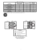
Table 6 – Accessory Usage

ACCESSORY

REQUIRED FOR LOW---AMBIENT

COOLING APPLICATIONS

(Below 55

F/12.8

_

C)

REQUIRED FOR LONG LINE

APPLICATIONS*

REQUIRED FOR

SEA COAST

APPLICATIONS

(Within 2 miles/3.22 km)

Ball Bearing Fan Motor

Yes

{

No

No

Compressor Start Assist Capacitor and Relay

Yes

Yes

No

Crankcase Heater

Yes

Yes

No

Evaporator Freeze Thermostat

Yes

No

No

Hard Shut---Off TXV

Yes

Yes

No

Liquid Line Solenoid Valve

No

No

No

Motor Master

or Low---ambient Pressure Switch

Yes

No

No

Support Feet

Recommended

No

Recommended

Winter Start Control

Yes

No

No

* For tubing line sets between 50 and 200 ft. (15.24 and 60.96 m) and/or 20 ft. (6.10 m) vertical differential, refer to Residential Piping and Longline Guideline.

{

Additional requirement for Low---Ambient Controller (full modulation feature) MotorMaster

r

Control.

24 VAC HOT

24 VAC COM

R

C

G

W/W1

Y/Y2

R

C

C

A/C

THERMOSTAT

Typical

FAN COIL

AIR

CONDITIONER

G

W2

HEAT STAGE 1

COOL STAGE 1

INDOOR FAN

24 VAC HOT

24 VAC COM

R

C

G

W/W1

Y/Y2

R

C

C

A/C

THERMOSTAT

Typical

FURNACE

AIR

CONDITIONER

Y

G

W

HEAT STAGE 1

COOL STAGE 1

INDOOR FAN

A02326

LEGEND

24-V FACTORY WIRING

24-V FIELD WIRING

FIELD SPLICE CONNECTION

CONTACTOR

C

A97368

Fig. 7 -- Generic Wiring Diagrams

(See Thermostat Installation Instruction

for specific unit combinations)

Summary of Contents for 105A

Page 1: ...CTRICAL SHOCK HAZARD Failure to follow this warning could result in personal injury or death Before installing modifying or servicing system main electrical disconnect switch must be in the OFF position There may be more than 1 disconnect switch Lock out and tag switch with a suitable warning label EXPLOSION HAZARD Failure to follow this warning could result in death serious personal injury and or...

Page 2: ...rigerant piping and service Allow 24 in 609 6 mm clearance to service end of unit and 48 in 1219 2 mm above unit For proper airflow a 6 in 152 4 mm clearance on 1 side of unit and 12 in 304 8 mm on all remaining sides must be maintained Maintain a distance of 24 in 609 6 mm between units or 18 in 457 2 mm if no overhang within 12 ft 3 66 m Position so water snow or ice from roof or eaves cannot fa...

Page 3: ...g Set lengths between 50 and 200 ft 15 2 and 61 0 m horizontal or 20 ft 6 1 m vertical differential 250 ft 76 2 m Total Equivalent Length refer to the Residential Piping and Longline Guide line Air Conditioners and Heat Pumps using Puron refrigerant 3 For alternate liquid line options on 18 42 size units see Product Data or Residential Piping and Application Guideline Install Liquid Line Filter Dr...

Page 4: ...d line temperature is higher than indicated or reclaim refrigerant if temperature is lower Allow a tolerance of 3_F 1 7_C Units with Indoor Piston Units installed with indoor pistons require charging by the superheat method The following procedure is valid when indoor airflow is within 21 percent of its rated CFM 1 Operate unit a minimum of 15 minutes before checking charge 2 Measure suction press...

Page 5: ... 32 88 31 86 30 84 29 82 28 317 94 34 92 33 90 32 88 31 86 30 84 29 326 96 36 94 34 92 33 90 32 88 31 86 30 335 98 37 96 36 94 34 92 33 90 32 88 31 345 100 38 98 37 96 36 94 34 92 33 90 32 364 104 40 102 39 100 38 98 37 96 36 94 34 374 106 41 104 40 102 39 100 38 98 37 96 36 384 108 42 106 41 104 40 102 39 100 38 98 37 395 110 43 108 42 106 41 104 40 102 39 100 38 406 112 44 110 43 108 42 106 41 1...

Page 6: ...ing may occur Charge must be weighed in Note Superheat _F is at low side service port Allow a tolerance of 3_F 1 7_C Note Indoor dry bulb between 70_F and 80_F 21_C and 27_C Table 4 Required Suction Line Temperature SUPERHEAT TEMP _F SUCTION PRESSURE AT SERVICE PORT PSIG 107 8 112 2 116 8 121 2 126 130 8 138 8 140 8 145 8 0 35 37 39 41 43 45 47 49 51 2 37 39 41 43 45 47 49 51 53 4 39 41 43 45 47 4...

Page 7: ...ds Use furnace transformer fan coil transformer or accessory transformer for control power 24v 40va minimum NOTE Use of available 24v accessories may exceed the minimum 40va power requirement Determine total transformer loading and increase the transformer capacity or split the load with an accessory transformer as required Final Wiring Check IMPORTANT Check factory wiring and field wire connectio...

Page 8: ...arge will be needed for longer line sets charge unit to nameplate subcooling Unit Size 15 ft 4 57 m Line Set Charge lb kg 113A 114CNA 114CNC 105A 18 4 10 1 86 4 77 2 16 4 5 2 04 4 87 2 21 24 4 22 1 91 4 20 1 91 4 20 1 91 4 60 2 09 30 4 90 2 22 5 67 2 57 5 67 2 57 5 67 2 57 36 5 00 2 27 5 42 2 46 5 42 2 46 6 40 2 90 42 6 07 2 75 7 90 3 58 7 90 3 58 7 46 3 38 48 7 00 3 18 8 31 3 77 8 31 3 77 8 31 3 ...

Page 9: ...trol Yes No No For tubing line sets between 50 and 200 ft 15 24 and 60 96 m and or 20 ft 6 10 m vertical differential refer to Residential Piping and Longline Guideline Additional requirement for Low Ambient Controller full modulation feature MotorMasterr Control 24 VAC HOT 24 VAC COM R C G W W1 Y Y2 R C C A C THERMOSTAT Typical FAN COIL AIR CONDITIONER G W2 HEAT STAGE 1 COOL STAGE 1 INDOOR FAN 24...

Page 10: ...uction line filter driers in line longer than 72 hours S Do not install a suction line filter drier in liquid line S POE oils absorb moisture rapidly Do not expose oil to atmosphere S POE oils may cause damage to certain plastics and roofing materials S Wrap all filter driers and service valves with wet cloth when brazing S A factory approved liquid line filter drier is required on every unit S Do...

Reviews: