


8
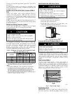
3--Phase Monitor
In 3--phase units a small circuit board is factory installed to monitor
line voltage. A small led will flash if a phase problem exists. See
code descriptions on monitor. If LED is flashing, disconnect
power to unit and interchange 2 field--wiring leads on unit
contactor.
A00010
Fig. 6 -- 3--Phase Monitor Control
(Applies to 3--Phase Units Only)
Table 5 – Three--Phase Monitor LED Indicators
LED
STATUS
OFF
No call for compressor operation
FLASHING
Reversed phase
ON
Normal
UNIT DAMAGE HAZARD
Failure to follow this caution may result in equipment
damage or improper operation.
Ensure compressor rotation is correct.
S
3--phase scroll compressors are rotation sensitive.
S
A flash LED on phase monitor indicates reverse rotation.
(See Table
5
)
This will not allow contractor to be energized.
S
Disconnect power to unit and interchange 2 field--wiring
leads on unit contactor.
CAUTION
!
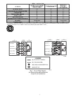
Sequence of Operation
Turn on power to indoor and outdoor units. Transformer is
energized.
On a call for cooling, thermostat makes circuits R--Y and R--G.
Circuit R--Y energizes contactor, starting outdoor fan motor and
compressor circuit. R--G energizes indoor unit blower relay,
starting indoor blower motor on high speed.
When thermostat is satisfied, its contacts open, de--energizing
contactor and blower relay. Compressor and motors stop.
If indoor unit is equipped with a time--delay relay circuit, the
indoor blower will run an additional 90 seconds to increase system
efficiency.
Check Charge
Factory charge amount and desired subcooling are shown on unit
rating plate. Charging method is shown on information plate inside
unit. To properly check or adjust charge, conditions must be
favorable for subcooling charging. Favorable conditions exist
when the outdoor temperature is between 70
_
F and 100
_
F
(21.11
_
C and 37.78
_
C), and the indoor temperature is between
70
_
F and 80
_
F (21.11
_
C and 26.67
_
C).
Follow the procedure below:
Adjust charge by adding or removing 0.6 oz/ft of 3/8 liquid line
above or below 15ft (4.57 m) respectively.
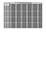
NOTE:
For 15 ft (4.57 m) line set charge, refer to the table below.
some units may require additional charge depending on size. Find
model size in chart below, reference factory charge on unit’s rating
plate and add additional charge if there is a difference. Additional
charge will be needed for longer line sets (charge unit to nameplate
subcooling).
Unit
Size
15 ft. (4.57 m) Line Set Charge lb (kg)
113A
114CNA
114CNC
105A
18
4.10 (1.86)
4.77 (2.16)
4.5 (2.04)
4.87 (2.21)
24
4.22 (1.91)
4.20 (1.91)
4.20 (1.91)
4.60 (2.09)
30
4.90 (2.22)
5.67 (2.57)
5.67 (2.57)
5.67 (2.57)
36
5.00 (2.27)
5.42 (2.46)
5.42 (2.46)
6.40 (2.90)
42
6.07 (2.75)
7.90 (3.58)
7.90 (3.58)
7.46 (3.38)
48
7.00 (3.18)
8.31 (3.77)
8.31 (3.77)
8.31 (3.77)
60
8.80 (3.99)
9.39 (4.26)
9.39 (4.26)
9.39 (4.26)
For standard refrigerant line lengths (80 ft/24.38 m or less), allow
system to operate in cooling mode at least 15 minutes. If conditions
are favorable, check system charge by subcooling method. If any
adjustment is necessary, adjust charge slowly and allow system to
operate for 15 minutes to stabilize before declaring a properly
charged system.
If the indoor temperature is above 80
_
F (26.67
_
C), and the
outdoor temperature is in the favorable range, adjust system charge
by weight based on line length and allow the indoor temperature to
drop to 80
_
F (26.67
_
C) before attempting to check system charge
by subcooling method as described above.
If the indoor temperature is below 70
_
F (21.11
_
C), or the outdoor
temperature is not in the favorable range, adjust charge for line set
length above or below 15ft (4.57 m) only. Charge level should then
be appropriate for the system to achieve rated capacity. The charge
level could then be checked at another time when the both indoor
and outdoor temperatures are in a more favorable range.
NOTE
: If line length is beyond 80 ft (24.38 m) or greater than 20
ft (6.10 m) vertical separation, See Long Line Guideline for
special charging requirements.
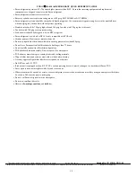
Final Checks
IMPORTANT
: Before leaving job, be sure to do the following:
1. Ensure that all wiring is routed away from tubing and sheet
metal edges to prevent rub--through or wire pinching.
2. Ensure that all wiring and tubing is secure in unit before
adding panels and covers. Securely fasten all panels and
covers.
3. Tighten service valve stem caps to 1/12--turn past finger
tight.
4. Leave Owner’s Manual with owner. Explain system opera-
tion and periodic maintenance requirements outlined in
manual.
5. Fill out Dealer Installation Checklist and place in customer
file.
CARE AND MAINTENANCE
For continuing high performance and to minimize possible
equipment failure, periodic maintenance must be performed on this
equipment.
Frequency of maintenance may vary depending upon geographic
areas, such as coastal applications. See Owner’s Manual for
information.


