


4
not rubbing against each other or any sheet metal or wires. Pay
close attention to feeder tubes, making sure wire ties on feeder
tubes are secure and tight.
Installing with Indoor Piston
Air Conditioner Matched with Factory Approved Piston
Indoor
Air conditioners may be installed with piston fan coils as a system
when the air conditioner and fan coil are listed as a system in the
AHRI directory. All rated piston fan coils are shipped with the
appropriate size piston for the equal tonnage air conditioner.
Matching air conditioners with piston indoors of larger tonnage
size requires a TXV.
Air Conditioner Applied as Replacement Component
If the air conditioner is installed as a replacement component in an
existing piston indoor system, the piston size in the indoor unit
should be changed to the size required for the air conditioner which
can be found in the Product Data
CAUTION
!
PRODUCT OPERATION HAZARD
Failure to follow this caution may result in equipment
damage or improper operation.
If using a TXV in conjunction with a single--phase
reciprocating compressor, a compressor start capacitor and
relay are required.
Units with Cooling Mode TXV
Units installed with cooling mode TXV require charging by the
subcooling method.
1. Operate unit a minimum of 15 minutes before checking
charge.
2. Measure liquid service valve pressure by attaching an accur-
ate gage to service port.
3. Measure liquid line temperature by attaching an accurate
thermistor type or electronic thermometer to liquid line near
outdoor coil.
4. Refer to unit rating plate for required subcooling temperat-
ure.
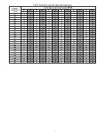
5. Refer to Table 2 --
Rating Plate (required) Subcooling Tem-
perature
. Find the point where required subcooling temper-
ature intersects measured liquid service valve pressure.
6. To obtain required subcooling temperature at a specific
liquid line pressure, add refrigerant if liquid line temperature
is higher than indicated or reclaim refrigerant if temperature
is lower. Allow a tolerance of
3
_
F (
1.7
_
C).
Units with Indoor Piston
Units installed with indoor pistons require charging by the
superheat method.
The following procedure is valid when indoor airflow is within
21 percent of its rated CFM.
1. Operate unit a minimum of 15 minutes before checking
charge.
2. Measure suction pressure by attaching an accurate gage to
suction valve service port.
3. Measure suction temperature by attaching an accurate ther-
mistor type or electronic thermometer to suction line at ser-
vice valve.
4. Measure outdoor air
dry bulb temperature with thermo-
meter.
5. Measure indoor air (entering indoor coil) wet--bulb temper-
ature with a sling psychrometer.
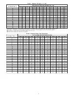
6. Refer to Table 3 --
Superheat Charging -- AC Only
. Find
outdoor temperature and evaporator entering air wet--bulb
temperature. At this intersection, note superheat. Where a
dash (----) appears on the table, do not attempt to charge sys-
tem under these conditions or refrigerant slugging may oc-
cur. Charge must be weighted in, adding or removing 0.6
oz/ft of 3/8 liquid line above or below 15 feet (4.6m) re-
spectively.
7. Refer to Table 4 --
Required Suction--Line Temperature
.
Find superheat temperature (from #6 above) and suction
pressure. At this intersection, note suction line temperature.
8. If unit has a higher suction line temperature than charted
temperature, add refrigerant until charted temperature is
reached.
9. If unit has a lower suction line temperature than charted
temperature, reclaim refrigerant until charted temperature is
reached.
10. When adding refrigerant, charge in liquid form into suction
service port using a flow--restricting device.
11. If outdoor air temperature or pressure at suction valve
changes, charge to new suction line temperature indicated
on chart.
12. Optimum performance will be achieved when the operating
charge produces 10
_
F suction superheat at suction service
valve with 95
_
F (35
_
C) outdoor ambient and 80
_
F (27
_
C)
dry bulb (67
_
F / 19
_
C) wet bulb) indoor temperature (DOE
“A” test conditions) at rated airflow.


