5-8
Section 5
Electrical Systems
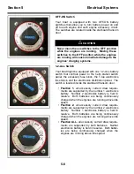
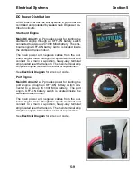
OFF-ON Switch
<RXU ERDW LV HTXLSSHG ZLWK WZR 2))21 EDWWHU\
VZLWFKHVWKDWDOORZ\RXWRWXUQEDWWHU\SRZHURQDQG
RIIWRHDFKHQJLQHDQGHDFKHQJLQHDFFHVVRU\FLUFXLW
The switches are located inside the starboard transom
door.
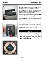
1-2-ALL Switch
Your boat might be equipped with one 1-2-ALL battery
switch that controls power to the helm station switch
panel, the accessory fuse block, the T-top electronics
fuse block, and the electronics distribution panel. The
switch is located inside the starboard transom door.
•
Position 1
- all accessory current draw require-
ments are supported by the number 1 electronics
battery. Number 2 electronics battery is held in
reserve. Both batteries are being continuously
charged when the engines are running above idle
speed.
•
Position 2
- all accessory current draw require-
ments are supported by the number 2 electronics
battery. Number 1 electronics battery is held in
reserve. Both batteries are being continuously
charged when the engines are running above idle
speed.
•
Position ALL
- all accessory current draw require-
ments are supported by both batteries. Neither
electronics battery is held in reserve. Both batter-
ies are being continuously charged when the
engines are running above idle speed.
!
CAUTION
Never move these switches to the OFF position
while the engines are running. Moving these
switches to the OFF position while the engines
are running will cause immediate damage to the
engines’ charging systems.
Summary of Contents for Boston Whaler 26 Justice Series
Page 14: ...1 10 Operator Notes...
Page 76: ...4 18 Operator Notes...
Page 94: ...5 18 Operator Notes...
Page 111: ......

