background image

3-16

Section 3

Fuel System

• If E-10 gasoline absorbs enough moisture, it can

suffer phase separation.  The ethanol and water

mixture will fall out of suspension and collect in

the lowest parts of the fuel system.  The ethanol

and water mixture can damage engines, clog fuel

filters, and corrode metal fuel system parts.  Fuel

tanks with E-10 gasoline should always be kept

as full as possible to reduce exposure to moisture

from condensation and humidity.

• Concentrations of ethanol greater than 10% can

change the physical properties of some rubber

and plastic fuel system parts such as gaskets,

hoses, tanks, and filters.  Regularly inspect all

non-metal fuel system parts for signs of swelling

or deterioration.  In some extreme cases, rubber

parts such as hoses and gaskets can actually

sweat liquid fuel.  Be alert for the odor of fuel or

small droplets of fuel near these parts.  Always

have fuel system repairs performed by a qualified

marine technician.

Summary of Contents for Boston Whaler 26 Justice Series

Page 1: ...ation Maintenance Manual Boston Whaler 26 Justice Series 2007 Brunswick Commercial Government Products All Rights Reserved 420 Megan Avenue Edgewater Florida 32132 USA www brunswickcgboats com 26 JUST...

Page 2: ...ographs and illustrations might not depict actual models or equipment but are intended as representative views for reference only The continuing accuracy of this manual cannot be guaranteed Certain fe...

Page 3: ...Propellers 2 14 Maneuvering 2 16 Load Distribution 2 18 Boat Trim Tabs 2 19 Stopping Procedure 2 21 Trailering 2 22 Safety Checklist 2 23 Towing 2 24 Backing 2 25 Lifting and Slinging 2 26 Gunwale Lif...

Page 4: ...ard Engine 5 9 Port Engine 5 9 Bilge Pumps 5 10 Helm Station Switch Panel 5 11 Accessory Fuse Block 5 12 T top Fuse Block 5 13 Electronics Distribution Panel 5 14 DC Circuit Distribution 5 15 Helm Sta...

Page 5: ...PFD s for your passen gers It is your responsibility to ensure that non swim mers wear PFD s at all times and that everyone wears a PFD during emergencies and severe weather The United States Coast G...

Page 6: ...that might allow carbon monoxide to collect in occupied spaces on your boat Remember these general precautions Avoid running engines or generator in confined areas such as boat houses Be aware of othe...

Page 7: ...at will help you evaluate your risk and response in case of an on board fire Fires Most marine fires result from spilled gasoline or oil accumulating in the bilge Careful use of on board fire extingui...

Page 8: ...ten to weather advisories before you start your trip and while you are underway Marine weather advisories are unique because of the special relationship between wind and waves The longer the wind blow...

Page 9: ...of the boat and its passengers even if the capacity limits have not been exceeded Capsizing Your boat might capsize due to improper loading improper operation or severe weather conditions Formulate a...

Page 10: ...nd the Certification Plate in the boat Consider reducing those loading limits during spe cial operations or adverse weather conditions Distribute the load evenly fore aft and port star board so that t...

Page 11: ...nded by California s Safe Drinking Water and Toxic Enforcement Act of 1986 amended through Proposition 65 WARNING A wide variety of components used on this boat contain or emit chemicals known to the...

Page 12: ...continually evaluate the sea state and boat performance Restrict passenger access to these decks if conditions warrant Keep accommodation decks free of loose gear WARNING Gelcoat surfaces are always...

Page 13: ...017136 Hi performance Boat 4 1817722 Customer Information Tag 5 1790729 Docking Lights 6 1811368 Carbon Monoxide 7 1846514 Dive Rescue Door 8 995704 Fuel Fill 9 1016963 Do Not Drill 0 1016898 Do Not D...

Page 14: ...1 10 Operator Notes...

Page 15: ...oad for trip T Fuel tank selector valves correctly set T Adequate oil level in reservoirs T Navigation lights operational T Signal horn and bell operational T Bilge pumps operational T Float switches...

Page 16: ...onditions Do not use the ignition shutoff switch to stop the engines during normal engine operation The ignition shutoff switch is connected to your cloth ing by a lanyard and clip If you move beyond...

Page 17: ...o a sturdy part of your clothing Do not shorten the switch lanyard It must be long enough to avoid inadvertent switch activation dur ing normal operator movement Refer to the engine operator s manual...

Page 18: ...one momentary push button Stop switch For each engine the panel has one Power On LED indicator light and one Alarm LED indicator light To start an engine the control shift lever must be in the NEUTRAL...

Page 19: ...an engine press the Stop switch until the engine stops Verify that the engine has stopped Look for a zero RPM reading on the tachometer Move the toggle switch to the OFF position For additional engine...

Page 20: ...nd oil supply T Prime engine fuel supply systems T Prime engine oil supply systems if the engines have not been operated in the last 30 days T Move control shift levers to NEUTRAL position T Attach ig...

Page 21: ...running before you shift into FORWARD or REVERSE Move the shift lever forward to select FORWARD gear for each engine Move the shift lever backward to select REVERSE gear for each engine Never shift d...

Page 22: ...ll reduce boat performance Excessive trim angle might cause propeller ventilation and engine over speed alarms WARNING Certain combinations of engine trim angle boat operating angle and boat speed can...

Page 23: ...ntrols have three engine trim switches The trim switch located on the port shift lever moves both engines at the same rate to change general boat angle The two individual trim switches are used to cha...

Page 24: ...d information about the gauges and their functions Review this general information about each gauge Tachometer The tachometer displays engine speed in revolutions per minute RPM You can take the gauge...

Page 25: ...gnition switch or power toggle switch is turned to the ON position The fuel gauge displays the approximate fuel level in the fuel tank The correlation between the gauge reading and fuel consumption is...

Page 26: ...er displays engine battery voltage mea sured in DC volts VDC Each engine has its own battery and charging system These readings indicate that engine battery system is in good condition Key OFF 0 volts...

Page 27: ...e trim gauge The trim gauge displays this value as relative Bow Up or Bow Down It takes specific experience with each boat engine pro peller combination to identify the best engine trim set tings for...

Page 28: ...ation about propeller designs and the correct propeller selection method You should always carry a spare propeller propeller hardware and propeller wrench onboard You should replace your propeller whe...

Page 29: ...decrease the engine s full throttle RPM at a rate of about 150 RPM per inch of pitch change Your boat might be equipped with one engine that is counter rotating which means that the port propeller rot...

Page 30: ...nd or current High traffic areas Confined or restricted areas Carrying hazardous cargo Compromised boat or engine systems Always follow established boating regulations and directions from boating law...

Page 31: ...ering wheel in a clockwise direction to turn to Starboard Use of the engine throttle in turning can greatly increase the performance of the boat while performing certain maneuvers To turn quickly to p...

Page 32: ...ll area Equipment and people are considered part of your non permanent load The non permanent load should be distributed evenly within the boat both fore aft and port star board The center of the non...

Page 33: ...t fore and aft Trim the boat port and starboard Improve ride smoothness Improve boat performance The trim tabs are located on the lower section of the boat s transom The boat trim tab operation is con...

Page 34: ...the PORT BOW DOWN switch the starboard trim tab will deploy If you press the STARBOARD BOW DOWN switch the port trim tab will deploy If you press both BOW UP switches both trim tabs will retract CAUTI...

Page 35: ...T Turn off fuel tank selector valves T Center the engines before tilting to avoid contact between the engine covers and any special tow ing equipment on your boat T Raise engines to full Tilt Up posi...

Page 36: ...ufacturer s owner manual for detailed information about the operation and mainte nance of this trailer Regulations controlling trailer equipment and manu facture vary from place to place You must veri...

Page 37: ...ow tie down link secured T Stern tie down straps secured T Trailer maintenance log current T Trailer surge or electric brakes operational T Trailer tires and spare in good condition T Trailer tire inf...

Page 38: ...ose attention to road and weather condi tions Always avoid situations where rapid acceleration or deceleration is required Double the recommended following distance for your towing speed Always be awa...

Page 39: ...onstantly Always know where the boat is in relation to any fixed objects Never accelerate in reverse Back up slowly When the trailer is straight behind the tow vehicle the rear of the trailer will mov...

Page 40: ...profession ally certified to lift at least 27 000 pounds 12 247 kg Failure of any lifting component could cause extensive damage to the boat seri ous injury or death WARNING Never use the boat s bow...

Page 41: ...attach a four point equal length harness that is professionally certified to lift at least 27 000 pounds 12 247 kg Attach at least two guide lines to control the boat while it is being moved Provide...

Page 42: ...the gun wales to indicate its location Protect the rub rails with carpet during the lift Attach at least two guide lines to control the boat while it is being moved Provide several spotters and handle...

Page 43: ...cause of any fuel leak immediately WARNING The components in your fuel system are designed to work with automotive gasoline con taining up to 10 ethanol by volume Using automotive gasoline with highe...

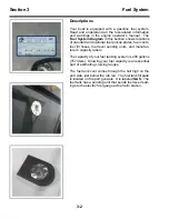
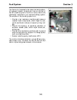
Page 44: ...fuel fill hoses fuel level sending units and manufac turer s capacity labels The capacity of your fuel tanking system is 200 gallons 757 liters Knowing your fuel capacity is an essential part of esti...

Page 45: ...en isolated metal components which might be sub ject to electrolytic corrosion caused by stray volt age Prevent the build up of electrical potential on exposed metallic parts which might cause per son...

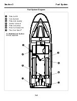
Page 46: ...em 1 2 3 5 7 4 6 7 Fuel System Diagram 1 Plate fuel fill 2 Vent fuel tank 3 Plate tank capacity 4 Sender fuel level 5 Plate fuel pickup 6 Hose fuel supply two 7 Filter fuel Racor See Maintenance Secti...

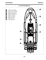
Page 47: ...tem Section 3 Access Plate Diagram 1 Locker bow anchor 2 Hatch Bomar storage 3 Bilge pump forward 4 Hoses fuel fill vent 5 Sender fuel level 6 Plate fuel pickup 7 Bilge pump aft 8 Plug bilge drain 1 2...

Page 48: ...fter testing coat all screws and terminals with liquid neoprene Repair The following general procedure covers the removal and installation of the bonding system wires Wires are accessed through the de...

Page 49: ...pres sure vacuum release safety overflow and flame arrestor Primer Bulbs Primer bulbs are installed in the fuel lines between the fuel water separators and each engine The primer bulbs are used to pum...

Page 50: ...r allow open flames or sparks within 50 feet of the fueling area when refueling DANGER A discharge of static electricity can ignite gaso line vapor causing serious injury death and destruction of prop...

Page 51: ...electricity discharge while fueling Always keep your boat in continuous contact with the water or a land based grounding system dur ing fueling Always keep the fuel nozzle in contact with the deck fil...

Page 52: ...ntinuously maintained until fuel flow has stopped Do not fill the tanks completely Allow a minimum of 2 of tank volume for expansion Allow for 6 expansion if the temperature of the fuel taken on board...

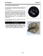
Page 53: ...e fuel gauge displays the approximate fuel level in the fuel tank The correlation between the gauge reading and fuel consumption is approximately linear from FULL to FULL The accuracy of the reading d...

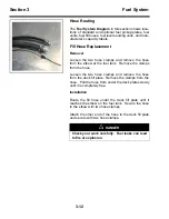
Page 54: ...tank Remove the clamps from the hose Loosen the two hose clamps and remove the hose from the deck fill plate Remove the clamps from the hose Pull the hose from under the deck plates slowly until it i...

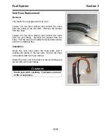
Page 55: ...the hose from the vent fitting Remove the clamps from the hose Pull the hose from under the deck plates slowly until it is completely free Installation Route the vent hose under the deck plate until i...

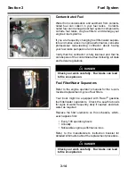
Page 56: ...taminated fuel following all state and federal regulations Fuel Filter Water Separators Refer to the engine operator s manual for the recom mended replacement cycle of fuel filters Your boat might be...

Page 57: ...ttention when used in your boat Follow these rules when using E 10 gasoline in your boat Read and understand all of the fuel related safety warnings and maintenance procedures outlined in this operato...

Page 58: ...ll as possible to reduce exposure to moisture from condensation and humidity Concentrations of ethanol greater than 10 can change the physical properties of some rubber and plastic fuel system parts s...

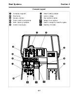
Page 59: ...nes 5 Helm steering hydraulic A Switch emergency shutoff engines 6 Control dual engine B Switches trim tabs U P TRIM D N TRIM U P D N DIMMER ANCHOR NAV LIGHTS RUNNING 7 AMP FWD BILGE PUMP MANUAL AUTO...

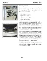
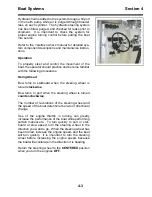
Page 60: ...ering wheel is turned The lock valve also con tains a pressure relief valve which provides over pres sure protection for the mechanical components the hydraulic hoses and the fittings When the steerin...

Page 61: ...Going Ahead Bow turns to starboard when the steering wheel is turned clockwise Bow turns to port when the steering wheel is turned counter clockwise The number of revolutions of the steering wheel an...

Page 62: ...g wheel is turned clockwise Stern moves to port when the steering wheel is turned counter clockwise The stern can be made to run straight in reverse by determining the proper rudder angle Experiment w...

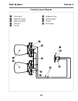
Page 63: ...Boat Systems Section 4 Steering System Diagram 1 Port engine 6 Hydraulic hoses 2 Starboard engine 7 Steering wheel 3 Steering cylinder 8 Fill port 4 Tiller arm 9 Helm pump 5 Tie bar 1 2 3 4 5 3 4 6 7...

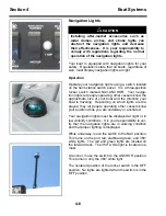
Page 64: ...ed at night or in low visibility conditions It is your responsibility to ver ify that the navigation lights are in working condition and that proper lighting is displayed While underway move the switc...

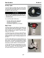
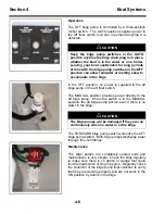
Page 65: ...port engine battery OFF ON switch Your bilge pump system consists of a forward 800 gal lon per hour GPH and an aft 1500 GPH pump Each pump is connected to a float switch that will activate automatical...

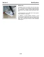
Page 66: ...ings Maintenance The bilge pumps are completely sealed units and maintenance is very simple Check the bilge regularly to make sure there is no debris or sludge that could foul the float switch or clog...

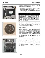
Page 67: ...er force on the trim tab surface cre ates upward pressure raising the stern and lowering the bow Properly sized trim tab planes improve the performance of your boat over wider load range weather and w...

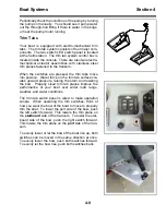
Page 68: ...the natural planing speed By pressing the control to the BOW DOWN position your trim tabs move down This will raise your stern and lower your bow getting the boat on plane sooner When learning to use...

Page 69: ...sing the trim function on the engine binnacle control until the engine propeller is parallel with the surface of the water If necessary readjust the trim tabs to fine tune the running attitude of the...

Page 70: ...growth should be removed from the actuator shafts by pressure wash ing Cold temperatures do not affect the trim tab system No winterization is necessary In saltwater to control galvanic corrosion a z...

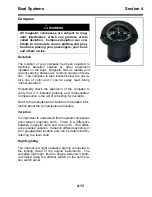
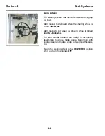
Page 71: ...on procedure Variation It is important to understand that magnetic compasses point toward magnetic north There is a difference between magnetic north and true north That differ ence is called variatio...

Page 72: ...s will not start due to low battery voltage use the battery parallel switch to provide power from the other engine starting battery With the engine key switch in the OFF position push and hold the bat...

Page 73: ...boat might be equipped with optional red cockpit night lighting The lights are used to illuminate the deck surfaces without creating glare at night The red cockpit lights are usually installed in pai...

Page 74: ...nics battery switch protects this circuit A two position rocker switch on the helm station switch panel controls the strobe light Use the siren control head to operate the various radio siren and publ...

Page 75: ...crew before beginning a tow operation Remove all non essential crew from the target boat Make sure that all tow rig components are of suffi cient capacity for the tow Set the tow rig as low and as cl...

Page 76: ...4 18 Operator Notes...

Page 77: ...corrosion Batteries CAUTION Batteries should always be enclosed in the cov ered battery boxes provided with your boat The boxes will contain any spilled acid as well as protect the battery terminals f...

Page 78: ...checks of electrolyte levels With proper care these marine grade batteries will last several years Maintenance Periodic battery maintenance is important to assure that the boat will be ready for opera...

Page 79: ...y appear to have dirt or corrosion on the terminals the batteries should be cleaned To clean the battery turn the battery switch to the OFF position Disconnect the battery cables from the terminals Re...

Page 80: ...attery fails to accept a charge from the engine alternators you should consider replacing it Check the engine alternators for proper function following the engine manufacturer s instructions Check for...

Page 81: ...n Proper grounding and bonding systems including zinc anodes and bronze plates will also help control corro sion of aluminum and stainless steel parts Grounding The negative terminals of all batteries...

Page 82: ...le connects the bronze plate to the negative buss bar The fuel tank fuel fill and all safety rails are connected to the negative buss bar with 8 awg green cables Also connected directly to the bonding...

Page 83: ...rovide power from the other engine starting battery With the engine key switch in the OFF position push and hold the battery parallel switch ON to either the left or right position Note this position...

Page 84: ...tery Number 2 electronics battery is held in reserve Both batteries are being continuously charged when the engines are running above idle speed Position 2 all accessory current draw require ments are...

Page 85: ...ct to a main two position heavy duty terminal strip located near the transom The main terminal strip simplifies engine removal for service or replacement See Electrical Diagram for wire color codes Po...

Page 86: ...made on the battery side of the OFF ON battery switch and is always powered regardless of switch position This circuit is protected by one 20 amp in line glass fuse located within seven inches of the...

Page 87: ...ctronics battery switch A four battery system will have a 1 2 ALL electronics battery switch The helm station switch panel has no connection to the negative side of the DC electrical system Any access...

Page 88: ...ve an OFF ON electronics battery switch A four battery system will have a 1 2 ALL electronics battery switch Ten branch circuits can be connected to the DC elec trical system at the accessory fuse blo...

Page 89: ...ics battery switch A four battery system will have a 1 2 ALL electronics battery switch Ten branch circuits can be connected to the DC elec trical system at the T top electronics fuse block The T top...

Page 90: ...witch A four battery system will have a 1 2 ALL electronics battery switch The electronics distribution panel has eight switchable circuit breakers controlled by one main 50 amp switch able breaker Th...

Page 91: ...e compass The navigation lights switch controls the red green and 360 white lights for night operations You can select all navigation lights while underway or the 360 white light by itself for anchori...

Page 92: ...even if there is no water in the bilge The FORWARD bilge pump switch works like the AFT bilge pump switch Both bilge pumps discharge water through thru hull fittings See Electrical Diagram for wire co...

Page 93: ...ten position blade fuse design It is powered by the number 6 main DC power distribution circuit from the electronics battery It can sustain a continuous load of 60 amps The T top electronics fuse bloc...

Page 94: ...5 18 Operator Notes...

Page 95: ...Shaft Length Dual 25 in 64 cm Boat Weight Hull No Engines 3700 lbs 1678 kg Load Capacity People Engines Gear 4300 lbs 1950 kg Swamped Capacity People Engines Gear 7300 lbs 3311 kg Maximum Engine Weig...

Page 96: ...orm of boat identification and must be included in all correspon dence related to your boat Failure to do so will create delays The engine and electronics serial numbers are also important when obtain...

Page 97: ...help protect it from deterioration caused by its working environment Your experience with your particular working environment will help determine the maintenance schedule Washing Exterior and interior...

Page 98: ...ed for gelcoat and fiberglass parts Follow the manufacturer s instructions carefully After compounding re wax all surfaces following the above steps Gelcoat Fiberglass Repair The interior and exterior...

Page 99: ...is insulated from the aluminum hardware Deck Hardware Clean deck hardware frequently with soap and water A glass cleaner is usually safe for stainless hardware Remove rust spots as soon as possible w...

Page 100: ...or chipped away If the powder coat gets chipped away touch up the part with a high quality acrylic enamel Hull Blistering The chemical and physical structure of all fiberglass boats is somewhat porou...

Page 101: ...er in a boatlift or on a cradle Be sure to use a bunk style design that supports the boat well Inspection Inspect the entire surface of the boat bottom on a fre quent basis Address any structural or c...

Page 102: ...uel and gear and mark the waterline Measure above the marked line about two inches for placement of the tapeline Use a vinyl rubber masking tape such as 3M 471 Preparation is the key to successful hul...

Page 103: ...tible the new paint will lift the old paint Never apply paint without first preparing the old painted surface Fuel System Your boat is equipped with one or more below deck aluminum fuel tanks that req...

Page 104: ...ystem serviced before running the boat It is good boating practice to rinse off your steering cylinder thoroughly with fresh clean water after each use Weekly check the steering fluid level in the hel...

Page 105: ...Check system for hydraulic leaks Refill and purge system as necessary Check steering hoses for signs of chafing and leaks Replace any steering hose that shows signs of chafing Inspect the bilge and mo...

Page 106: ...rway reducing the possibility of damage to the bat teries and other equipment in the storage area DANGER Never use an open flame in the battery storage area Avoid striking sparks near the battery A ba...

Page 107: ...stance and service life These batteries are classified as non spillable and do not require periodic checks of electrolyte levels Maintenance Periodic battery maintenance is important to assure that th...

Page 108: ...should be cleaned To clean the battery turn the battery switch to the OFF position Disconnect the battery cables from the terminals Remove the negative black cable first Remove the battery from the pl...

Page 109: ...freezing Outboards You must protect your outboards from freeze damage and from corrosion caused by extreme changes in temperature Store your outboards in the vertical operating position to avoid trapp...

Page 110: ...e and use a fuel stabilizer additive following the engine manufacturer s recommenda tions Once the stabilizer has been added to the fuel system run the engines for at least ten minutes to ensure that...

Page 111: ......
Page 112: ...World class support for World class boats...

Reviews: