17
l
© Brüel & Kjaer Vibro GmbH/4 mm ds821 / 21.7.15 / technical specifications subject to change / C104958.001/ V02
EN
4 mm displacement sensor system series ds821
Instructions
| Installation
4.1
Assembling the displacement sensor
4.1.1
Displacement sensor for front-side mounting
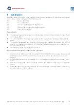
The front side-mountable displacement sensors are supplied with two nuts. You can use these
nuts during assembly to position the displacement sensor and lock it in place after adjustment
(4.4 Setting up the measuring chain and the displacement sensor). Depending on the applica-
tion, the sensor can be mounted forward-facing either within a machine or outside of a machine
or through the machine housing. To avoid measurement errors, we recommend in all cases that
the sensor be mounted with the help of a suitable sensor holder. The sensor holder must be
mounted in a position where it cannot move relative to the object to be measured during
machine operation.
1.
Remove the protective cap from the sensor tip.
2.
Attach the displacement sensor using a sensor holder suitable for the chosen type of
assembly.
3.
Position the sensor so that it lies vertically to the measuring track.
4.
Take care to avoid direct contact of the sensor tip with the object to be measured. Adjust
the sensor through the display of the measured gap voltage.
5.
Install the extension cable. For fixing with cable clamps, we recommend the use of a suita-
ble protective conduit.
6.
For assembly within the machine:
Seal the opening in the housing with a bulkhead receptacle to prevent medium inside the
machine (e.g. gas or oil) escaping to the outside.
Assembly of sensor within the machine housing
Bulkhead receptacle
Sensor holder
Seal thread
Assembly of sensor outside the machine housing
Displacement sensor
Sensor holder
Displacement sensor


