


7-26
7.5.15 Updating of Property Data
(Function code 68)
Function
To keep the print quality, the controller optimizes the drive conditions of individual print head
units, paper feed rollers, paper ejection rollers, and air pump & motor modules according to their
property data. In the case of the print head unit, for instance, the controller optimizes the head
drive strength, ink jet-out timing and other drive conditions according to the electromechanical
properties unique to individual print heads and ambient temperature.
Those property data is stored in the EEPROM on the driver PCB and their property codes are
printed on their property labels which are attached to the rear left side of the machine (with the
battery cover* or rear cover S** removed).
*
For the MFC4820C
**
For the MFC4420C
If you replace any of the print head unit, paper feed roller, paper ejection roller, or air pump &
motor module with a new spare part, then you need to enter its property code printed on the
property label (that comes with the new spare part) and replace the old property label on the rear
left side of the machine with the new one. If the old part may be used in future, store the old
property label also with the old part.
Operating Procedure
(1) Press the
6
and
8
keys in this order in the initial stage of the maintenance mode.
(2) For the print head unit, press the
2
,
5
,
8
,
0
keys in this order.
For the paper feed roller, press the
0
,
1
,
2
,
3
keys in this order.
For the paper ejection roller, press the
0
,
4
,
5
,
6
keys in this order.
For the air pump & motor module, press the
0
,
7
,
8
,
9
keys in this order.
The current property data stored in the EEPROM appears on the LCD and the equipment is
ready for entry.
(3) Check the property label that comes with a new spare part (print head unit, paper feed roller,
paper ejection roller, or air pump & motor module) and then enter the property code.
The code to be entered is: 14 digits for the print head unit, 4 digits for the paper feed roller
and ejection roller, and 19 digits for the air pump & motor module.
If you enter 4 digits for the paper feed roller or ejection roller, the 5th character automatically
appears. Check that the displayed 5th character is the same as that on the property label. If it
is not, enter the 4 digits again.
For the air pump & motor module, enter the 9 digits, press the
Fax Start
key, and then enter
the remaining 10 digits.
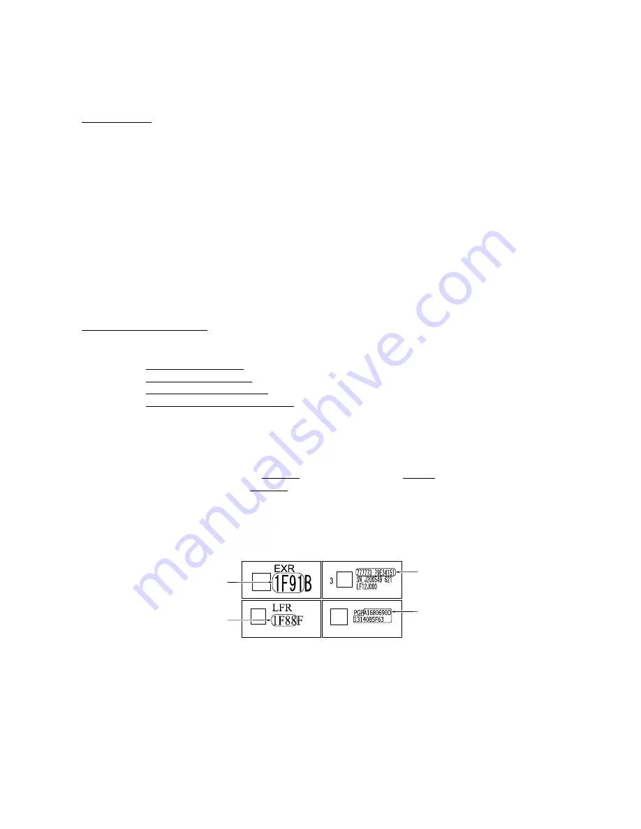
For air pump & motor module
For paper feed roller
For ejection roller
For print head unit
NOTE:
To enter letters "A" through "F," press the
1
through
6
keys while holding down the
#
key, respectively.
(4) Press the
Menu/Set
key.
The equipment beeps, shows the "INPUT ACCEPTED" on the LCD, and writes the entered
property code into the EEPROM. Then it returns to the initial stage of the maintenance mode.
NOTE:
If the entered data contains any checksum error, the equipment beeps, shows the
"INPUT ERROR," and then returns to the ready-to-enter state. Go back to step (3).
Summary of Contents for MFC-4820C
Page 1: ...FACSIMILE EQUIPMENT SERVICE MANUAL MODEL MFC4820C MFC4420C ...
Page 6: ...CHAPTER 1 PARTS NAMES FUNCTIONS ...
Page 13: ...CHAPTER 2 SPECIFICATIONS ...
Page 19: ...2 5 2 1 4 Environmental Conditions ...
Page 26: ...CHAPTER 3 SETTING UP OF THE MACHINE ...
Page 29: ...3 2 3 2 UNPACKING THE MACHINE The equipment consists of the following major components ...
Page 40: ...CHAPTER 4 THEORY OF OPERATION ...
Page 76: ...CHAPTER 5 ROUTINE MAINTENANCE ...
Page 84: ...CHAPTER 6 DISASSEMBLY REASSEMBLY ...
Page 114: ...6 29 6 1 11 Speaker 1 Pull the speaker and its spring out of the lower cover ...
Page 136: ...CHAPTER 7 MAINTENANCE MODE ...
Page 145: ...7 8 Scanning Compensation Data List ...
Page 160: ...7 23 1st sheet 2nd sheet Vertical Alignment Check Patterns and Head Skew Check Pattern ...
Page 162: ...7 25 Margin Check Patterns ...
Page 170: ...CHAPTER 8 ERROR INDICATION AND TROUBLESHOOTING ...
Page 197: ...MFC4820C MFC4420C Appendix 1 Serial No Descriptions ...
Page 205: ...App 2 4 Click Finish to return to Windows ...
Page 209: ...MFC4820C MFC4420C Appendix 3 EEPROM Customizing Codes ...
Page 212: ...MFC4820C MFC4420C Appendix 4 Firmware Switches WSW ...
Page 252: ...App 4 40 WSW48 to WSW50 Selector No Function Setting and Specifications 1 8 Not used ...
Page 253: ...MFC4820C MFC4420C Appendix 5 Re Packing Instructions ...
Page 255: ...App 5 2 2 Place the machine in the original box with the original packaging material ...
Page 256: ...MFC4820C MFC4420C Appendix 6 Wiring Diagram ...
Page 259: ...A Main PCB 1 5 ...
Page 260: ...A Main PCB 2 5 ...
Page 261: ...A Main PCB 3 5 ...
Page 262: ...A Main PCB 4 5 ...
Page 263: ...A Main PCB 5 5 ...
Page 264: ...B Driver PCB ...
Page 265: ...C NCU PCB ...
Page 266: ...D Control Panel PCB ...
Page 267: ...E Power Supply PCB ...


